Arduino based Rocket Telemetry System.

Hello all,

I am a Engineering student working on my level 1 and 2 Tripoli certification for my rockets. I want to build a all in one telemetry system with a arduino based device.

My plans are,

GPS LS20031 32channel
Arduino Duemilanove/Mega
2 Xbee Pro 900's
ADXL 345 or similar.

I am Slightly confused, would it be possible to use these for a wireless streaming of data to a laptop out on the field?

I do have micro controller experience and C programming experience.

The rockets are high powered G and above, so weight is not cruical. But Lighter is better ;D

I was hoping to build something like this, but better looking and more functional

Can this all be done on a single Arduino unit? Considering He did it with a single PIC?

Thanks,
Brian

"I am Slightly confused, would it be possible to use these for a wireless streaming of data to a laptop out on the field? "

Yes. I'll be flying something similar a little later today, weather permitting. I've flown a homemade XBee-based telemetry system successfully 7 times, sending altitude data taken from a Perfectflite MAWD altimeter, sent directly to an XBee (no intervening microprocessor), and to a receiving station on the ground.

The GPS half of your project could do the same thing. An XBee will automatically transmit whatever serial data are sent to its DIN pin. GPS units typically send out NMEA strings as serial data, at 4800 baud (8N1), so if you change the interface rate of your XBee to 4800 and make sure you're using the appropriate data level, you can transmit GPS data without even needing the Arduino. I've built and ground-tested a board that does exactly that. If I haven't forgotten any parts, it'll fly later today (in a 4" diameter rocket on some kind of I motor).

If you were to use a GPS that had 3.3V output, all you'd need for this would be power to the XBee and GPS, and a single wire from the GPS output to the XBee DIN pin, and you're set. If the GPS is 5V you'll need level-shifting, and dual power supplies (as you see in the project that you linked to).

The ADXL 345 will be a bit more complicated, as will putting both sensors through the same XBee at once. It would be possible to connect the ADXL's analog output to one of the XBee I/O pins, set it all up for analog line-passing, and set up a system for reading the analog voltages on the ground side, to again avoid having to fly the Arduino. I'm not certain that you could do that and also have the GPS data sent out from the same XBee, though.

The alternative is to have the Arduino read the data from both the GPS and the ADXL 345, and then send them out in a certain format through its serial port to a level shifter to the XBee DIN pin (again, unless you're using a 3.3V Arduino, in which case you just need a single wire to the XBee).

On the receiving end, if all you want is a file with the data, connect an XBee through a USB board to your laptop, send the data to a terminal program, and turn on the "capture" function before you fly. Alternatively, you could set up PLX_DAQ software and send the data directly to an Excel file, for on-the-fly graphings of the acceleration. I did that with the altitude data. It's pretty cool, though it requires a few extra steps.

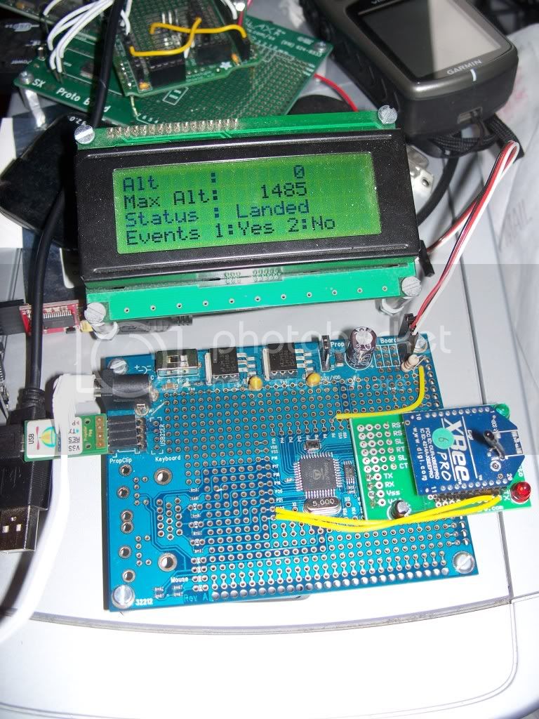
I'm using regular 2.4 GHz XBee Pro modules, rather than the higher-range 900 MHz ones. I've flown to about 3200 feet with my system, without any loss of data at all, even right up to landing. Of course the 900 MHz modules will give you more range (at greater expense), and otherwise should set up exactly as the 2.4 GHz ones do.

The versions I've flown so far were just wires plugged into the appropriate places. Today's devices are mounted on pc boards that I designed myself, and had BatchPCB produce. I didn't use SMT parts, but there'd be obvious advantages to doing so (smaller size, more resistance to shocks from the ejection charges). If I get ambitious and find the time, I'll make SMT versions.

I just took a look at the GPS you're using. It's a bit unusual, in that it uses 9600 Baud, so you shouldn't need to change the comm speed of the XBee (which defaults to 9600). It also has some extra capabilities that you might be able to use, but that I can't help you with. Here's a page that looks very helpful, though:

Sylvie,

I am familiar with the Xbee radio setups, but I have been using the RS232 Board to communicate with it and a Atmega32, for a small tank type robot.

What I really should have asked is, that, can the Arduino be used to take in multiple signals, analog from the accelerometer, digital from the GPS and maybe even a temperature reading? Possibly will I need to use the I2C? or can it all be done using the serial setup?

The way i look at it, the GPS can be hooked up like this.

Bottom page picture in comments. Then I can also attach the ADXL345 like:

And this will not use the same communication lines for eather component.

I checked out the GPS drone site. Seems like the way they set it up would work well for what I am doing, so I will probably set it up that way.

Also what is the format for the outputs on the arduino? I assume it is some sort of TTL or RS232.

I also have the resources for CNCing double-sided boards, or if necessary, acid etching them, but the plug-n-play technology the arduino offers is very attractive.

Sorry for all the questions ;D

Brian

What kind of G-force are you dealing with this might be a factor if its high enough.

The ADXL345 can handle -/+18g's, assuming I am not going for any "bowling ball" motors, I think it will handle launches ok. Unless analog makes a 20-30g 3axis accelerometer, this one seems to take the ticket

Also, can the arduino handle a xbee on top of all of this?

Brian

Also, could I use shields and just stack em? or should I just buy the parts a fiddle with breadboarding, then etch my own stuff?

Brian

"What I really should have asked is, that, can the Arduino be used to take in multiple signals, analog from the accelerometer, digital from the GPS and maybe even a temperature reading? Possibly will I need to use the I2C? or can it all be done using the serial setup?"

The Arduino can take in multiple signals. Once you've hooked up the hardware the way you referenced, it's just a matter of programming, and it looks like most of the code you need is already out there.

"Also what is the format for the outputs on the arduino? I assume it is some sort of TTL or RS232"

If you're talking about output to the XBee, you'll use a serial connection, either through the Arduino's built-in hardware serial port on pins 0 (RX, which you're probably not using) and 1 (TX), or by setting up a software serial port through one of the other pins (and the software serial library). I'm doing the latter with an Arduino and an XBee on a project - it works fine.

"I also have the resources for CNCing double-sided boards, or if necessary, acid etching them, but the plug-n-play technology the arduino offers is very attractive."

Yes, it is. You will need to be careful, of course, to make sure that your connections aren't going to come loose under the shock of liftoff and of the ejection charges. I wouldn't assume that wires simply plugged into the headers would stay there during flight, but I'd expect a little tape to do the job. If you're new to rocket electronics, get some help from the local Tripoli guys on securing batteries. We had a new flyer's first dual deployment flight fail yesterday due to shifting batteries (fortunately no damage, and she made a successful second attempt).

Thanks Sylvie! That really cleared up a ton of questions I had.
Since I also dont want this thing to be to huge, I will probably skip on the sheilds and just breadboard it, then etch out a custom board to hold the accelerometer, GPS and Xbee.

I think I might also need a Logic Level converter for the GPS? or can I just get a 3.3v Vreg and use 5v TTL to communicate?

Thanks,
Brian

I think you might have sold me on that GPS unit - it looks pretty decent.

I think that if you're only reading data from the GPS to the Arduino you won't need level conversion, but if you're using the Arduino to change the GPS settings as well, you'll need level conversion. I'm not very knowledgable about this, though. You might want one of the experts to confirm this.

You WILL need level conversion from any 5V inputs to the XBee DIN pin, though.

I flew my pullpin telemetry unit yesterday, and it worked just fine. Unfortunately, my main snarled, and I destroyed the electronics bay, but the electronics themselves are fine. A little rebuilding and I'll be at it again by the next launch.


Today I ground tested my XBee GPS transmitter. Again, I'm just using standard 2.4 GHz XBee Pro modules.


I tested out to .27 miles, which isn't very far, but there were guys with live ammunition in their shotguns further back in the woods, so I needed to stick close. I did lose contact down in a gully, but it picked up gracefully on the other side, as you can see in those images. In the third image, the red line is the track from my transmitter, and the blue line is from my handheld Garmin unit. The transmitter track ends early because my laptop (back at the rangehead) went into sleep mode at that point.

Ok cool, just reading in from the GPS is all I should need, but if I buy a Logic level converter I might as well wire up the GPS and the xbee while im at it.

Nice looking xbee board, is that custom? I might make one similar, but I will mount my Xbee, GPS, and Accellerometer on it with a possible Boarduino or Arduino.

Im gonna stick with the 900's for now, the range seems to be pretty nice, especially if I put it in a large rocket I am planning. Rocksim says it will reach 11,000ft!!!!

Thanks again

Brian

Yes, I designed my own boards for these projects. I flew a breadboarded version 7 times last year, all successfully, but it was just screaming for custom pc boards.

If I were starting from scratch right now, I'd definitely use the 900 MHz versions. They're not that much more expensive, and should give quite a bit more range. But I already have several of the 2.4 GHz versions from other projects, and they do seem to live up to the 1 mile range they claim.

Sounds good, now I need to look up a way to display the data I get, live on my laptop. Probably some sort of program that reads the data directly from the xbee, or a file created by it.

Any ideas there?

Brian

Directly from the XBee?

The simplest way to collect the data is to simply dump them all into a file using the capture function of a terminal program. But that doesn't display nicely formatted data in real time. If you're willing to just capture the data in real time and do all of the nice analysis and display later, this is by far the easiest way.

Your alternatives are:

1 - Use a microprocessor on the receiving end, which parses the data and displays the data you want in a nice format on an LCD screen. That's what I'm currently doing on my telemetry project. Of course that's not "directly", and it requires a second processor on the ground.

2 - Write a program to run on your laptop that parses the data and displays them. Visual Basic is one option (the only one I've ever used), but there are a lot of programming languages that can parse incoming serial data and display those you want. Here's the page that helped me the most with that route:

http://www.theabramgroup.com/basicstamp/

3 - Use PLX-DAQ (available for free download from Parallax.com) to dump the data into an Excel file on your laptop. PLX-DAQ actually IS Visual Basic, some macros written specifically for reading incoming serial data to Excel. I've used this as well with the first version of my telemetry program, creating real-time graphs of the rocket's altitude. This is probably easier than writing your own standalone Visual Basic program, unless you've got VB experience.

http://www.parallax.com/tabid/441/Default.aspx

Sorry if I'm belaboring the obvious here. I'm sorta thinking aloud as well as trying to answer your question.

I dont have VB expierience, but I do know Java pretty well, and C very well.

I needed a Java project anyway, so I think I will look into that. I will have to look into parsing the data as it comes in so I can have some pretty graphics, showing G's altitude, etc.

Thanks,
Brian

I've been advised that civilian GPS units are limited in performance. They won't work at over 15000 ft or over 250MPH. Otherwise we would have guided IED's.

I've been advised that civilian GPS units are limited in performance. They won't work at over 15000 ft or over 250MPH. Otherwise we would have guided IED's.

Not true.

The restriction is at 60,000ft. I'm not sure what the exact speed value is.

There is a requirement that they don't do BOTH at the same time. You can do one or the other. Some manufacturers however take the easy way out and lock out when EITHER occurs.

Here's a list maintained by high altitude enthusiasts listing which modules do/don't work above the altitude limit

http://showcase.netins.net/web/wallio/GPSrcvrsvs60kft.htm