I'm working on a haunted hallway school event. The lighting in the hall is all controlled by an arduino. More things have been added over the years and the wiring is getting out of hand for something that needs to be put up and taken down the same day.
With that in mind I'm thinking about making a series of "nodes", with one wire bundle of three wires from node to node so it's really easy to put up and take down. Each node would go on the roof in place of the ceiling lights, and include one of the ceiling lights on the bottom. Speakers and other lights could use much shorter cable runs to the nearest node, instead of running back to a central location.
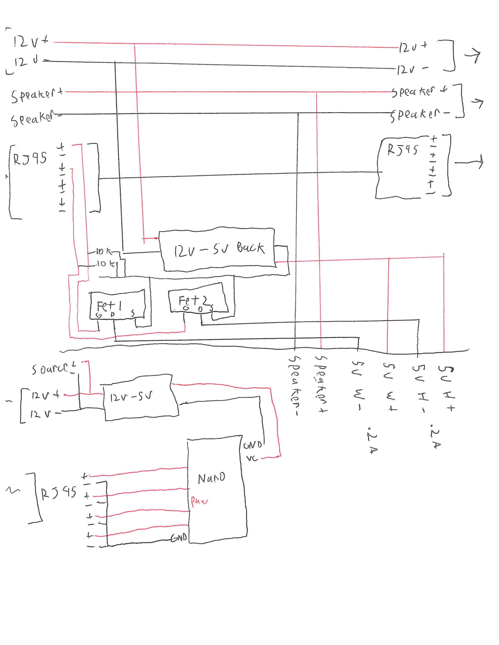
My thought is to use a 12v mainline, with buck converters to the 5v leds in each node. Given the length and number of lights, combining it all on 5v is getting a bit iffy.
The second wire is for speakers, which are their own separate setup, and only included as part of the node.
Last is ethernet for arduino to n-channel mosfet communication, since I have plenty of cable on hand. The diagram currently only uses two mosfets and 5v outputs, but two more could be added. The plan is that each wire pair is passed from node to node, so all of the lights on each pair will behave the same.
My main questions are does all of this seem reasonable? Also, at each node, should the ethernet grounds be connected to ground again, even though they are connected to ground at the arduino side?
The diagram is hand drawn, so please forgive some of the line gaps as well as my handwriting.