I'm trying to connect an Arduino board inside a weight indicator (Yoshua XK3190-A12E). The weight indicator is connected to a load cell with a 9 pin port. I cut the Signal+ (IN+) as it carries the weight measurement data from the load cell. Now, I used a voltmeter to check if there is voltage going through both the indicator and Arduino. However, the readings on the analog pin from Arduino remains 0. I tried checking for voltage on the Arduino alone using a battery and alligator wires and it recorded some voltage. Is there a way we can read the voltage passing through on BOTH the weight indicator and Arduino? I'm very new to this
Please provide a link to the datasheet of that weight indicator.
does this help?
Maybe. Can you post a schematic of how you have everything connected so far?
Have you ensured that the sensor and the Arduino have their GNDs connected?
PS: voltage doesn't "flow"! Current flows. Voltage is a potential; it doesn't move.
it looks like this
           +--------------+
           |              |
           |  Weight      |
           |  Indicator   |
           |              |
           +------+-------+
                  |
                  | S+
                  |
                 +++
                 | |
                 | | Potentiometer
                 | |
                 +++
                  |
                  | GND
                  |
                  +---> GND (Arduino)
                  |
                  |
                  +---> A0 (Arduino)
So according to your schematic you have A0 connected to GND. Which means that you will always read 0.
1 Like
Sorry, I should have been more specific: a full schematic of the entire system. Including power supply and ground connections between all parts. Thanks!
That document is just a datasheet, and gives little useful information.
The XK3190-A12E User Manual is a better document to use.
@mlouise16 you are trying to directly read the load cell of the scale. This is not possible using just an analog read.
You will make faster better progress if you instead switch to using the scale's digital interface via serial communication to you Arduino board.
See the user manual for details.
a7
The In+ and In- signals from the load cell only vary by a maximum of 6mV to 20mV.

You would need to amplify the voltage difference between In+ and In- before feeding the combined signal to an Arduino.
This could be done using an instrumentation amplifier.
In post #5, you show your connection going to S+.
S+ is part of the Excitation circuitry and should not change in value.
Here is an edited version of the load cell connection information from the manual.
(it is on two separate pages in the manual.)

In+ and In- are the two signals that you require.
Even if you are successful in making a circuit that works with an Arduino, then it would require calibrating separately. It is highly likely that the reading on the Arduino would not match the reading on the existing display.
In my view, the way to go is reading the RS232 data from the scales serial output (as mentioned by alto777 in post #9.)
Looking just a bit closer at the documentation has confused me.
I can't tell for sure if that jack gives you access to an internal load sensor, or if it is where you can attach your own load sensor.
I don't see two DB9 connectors, so the serial signals look like they are conflicting with some of those load sensor signals.
@mlouise16 can you tell us you have a weighing platform upon which that to be weighed is placed, that is already part of or connected to the thing you are trying to analaogRead from?
Maybe snap a few pictures showing what you are dealing with. Include pictures of the ports or jacks and the buttons and the display so it's almost like we have one ourselves.
a7
The serial output is not from a DB9 connector, but from a 5 pin circular connector.

Here is a photograph I managed to find of the connector:
Most photos seem to show a fuse holder in the position occupied by that connector.

Can you load an image of the inside of the weight indicator (Yoshua XK3190-A12E)?
I expect it has:

There is another version without the RS232 connector (see bottom edge on right GND, TXD, RXD):
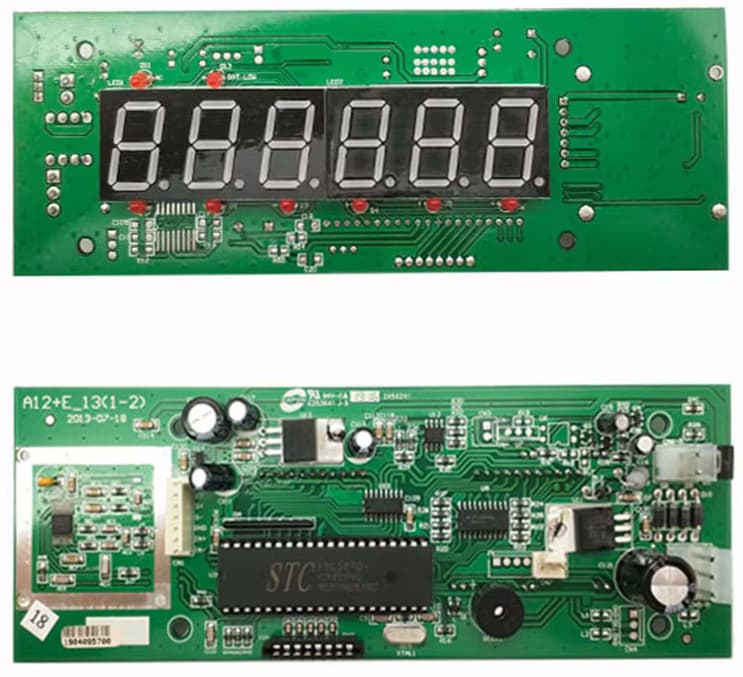
The RS232 version also has extra components on the flip side underneath the first 2 digital segments, probably including a 16-pin MAX3232CSE DIP with it's supporting resistors/caps.
Can the A12E-NoRS232 board generate TTL data? Does it need supporting components? What about VCC?
RS-232 - Wikipedia3-wire and 5-wire RS-232
A minimal "3-wire" RS-232 connection consisting only of transmit data, receive data, and ground, is commonly used when the full facilities of RS-232 are not required. Even a two-wire connection (data and ground) can be used if the data flow is one way (for example, a digital postal scale...)
More on this module at: Read from weighing scale using RS232
Also same issue at Need help with this kind of Rs232
This topic was automatically closed 180 days after the last reply. New replies are no longer allowed.