4x Load Cells Hx711, smart weight scale

Hello everyone,

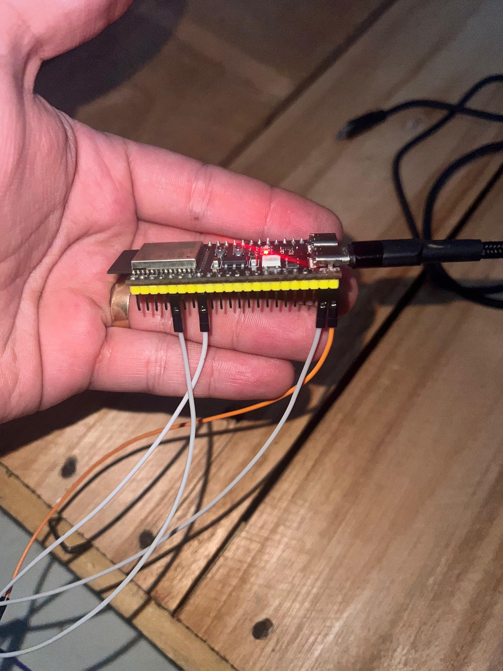
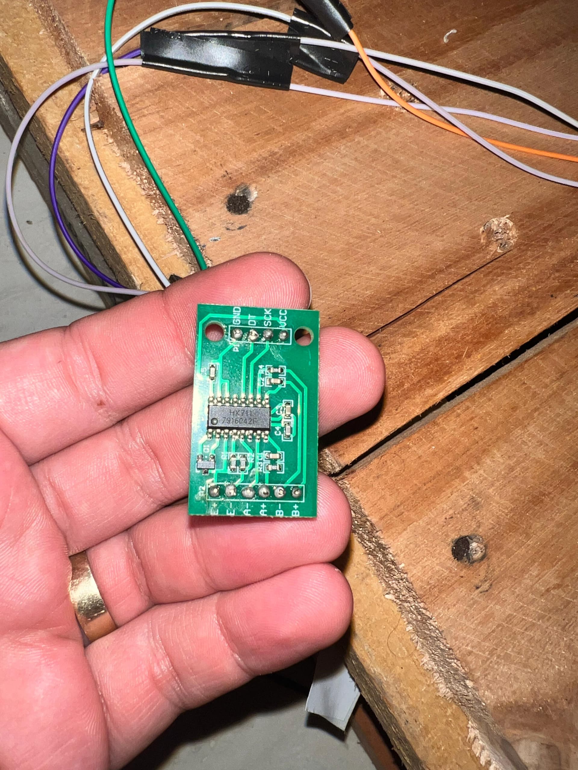
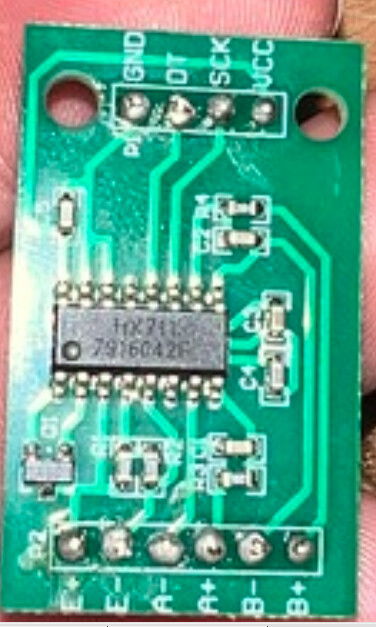
I’m trying to build a digital scale that will upload data to a database so I can monitor the stock levels of a specific part over time. I’m using four 50kg load cells, an HX711, and an ESP32-S3 DevKitC-1.

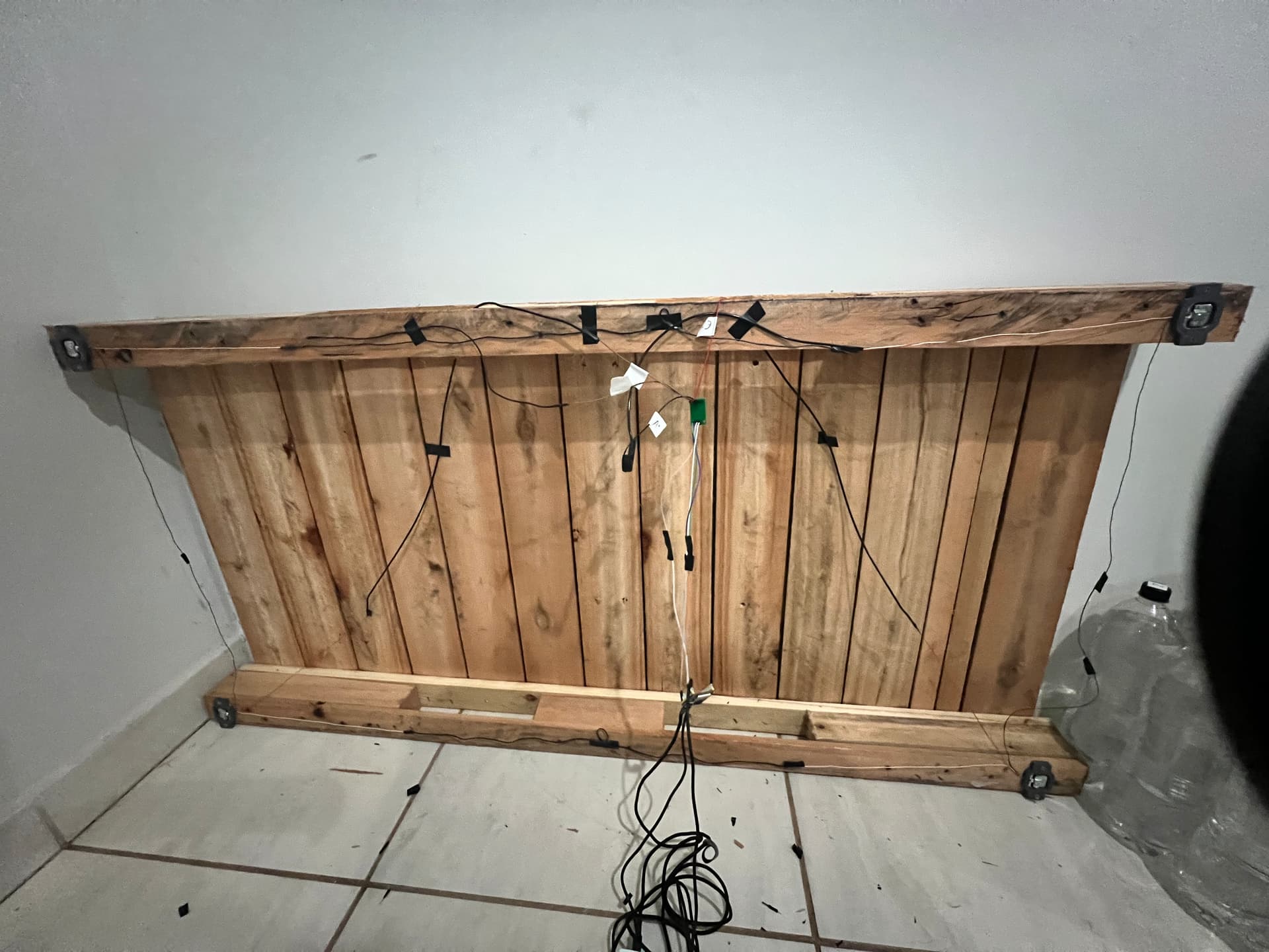
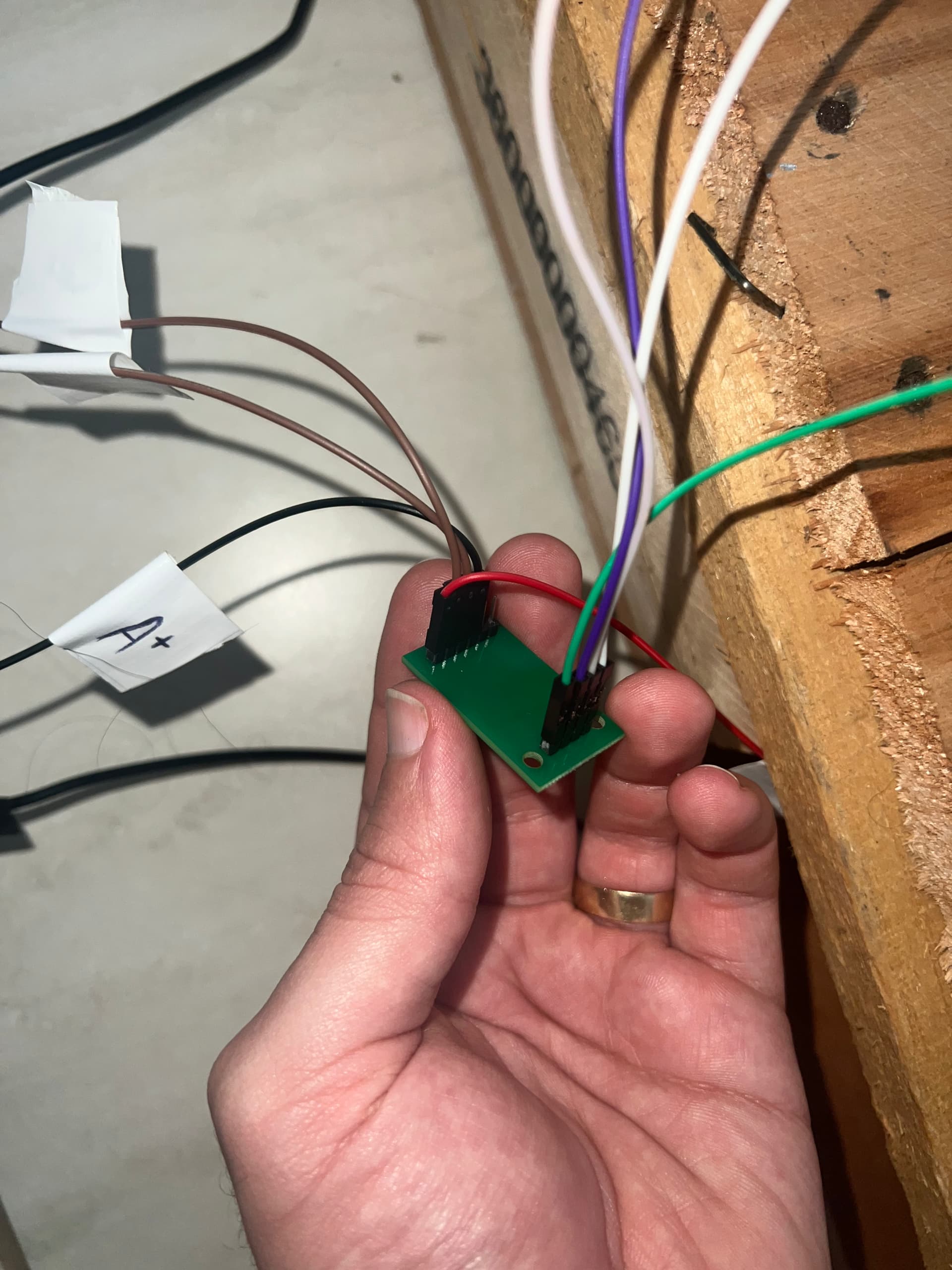
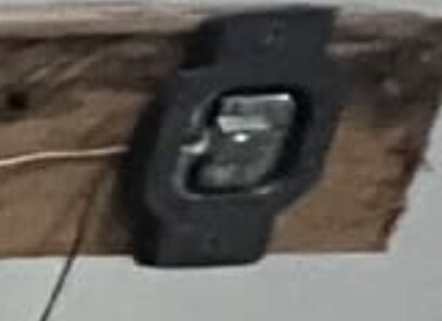
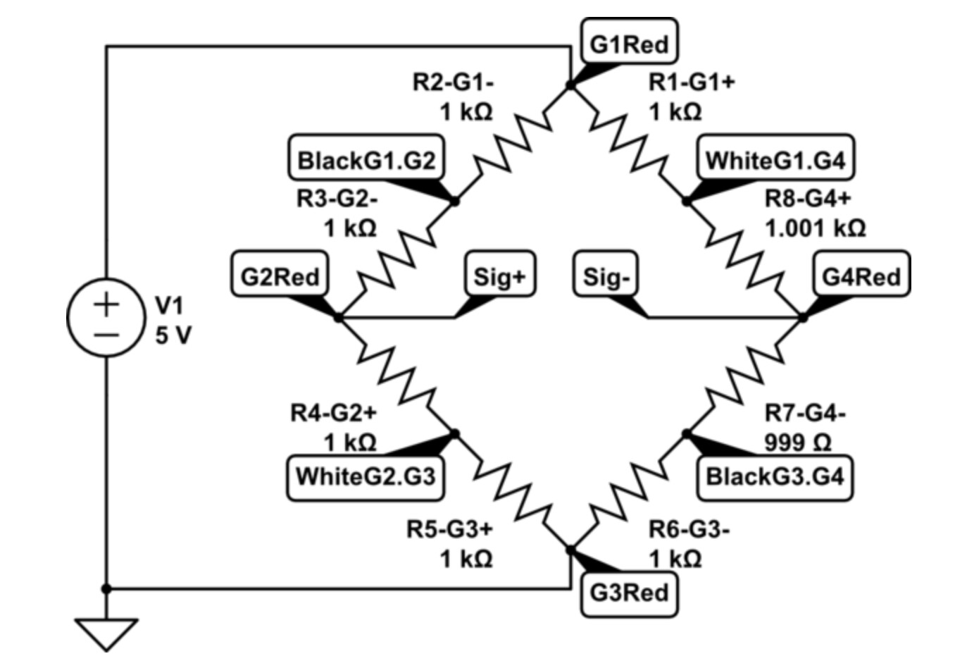
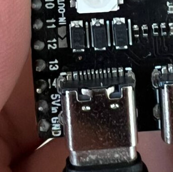
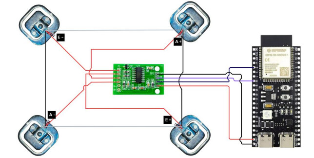
I assembled everything following the diagram below, where you can see both the theory and an actual photo of the setup, including all the connections.

However, the readings are very strange. I ran some tests I found in other posts, and one of them was to measure the resistance between the wires of the load cells. Here are the results, using a multimeter set to 20k ohms:

Top left :white_check_mark:
20k - 1.97 (black-white)
20k - 0.98 (black-red)
20k - 0.98 (red-white)

Bottom left :white_check_mark:
20k - 1.97 (black-white)
20k - 0.98 (black-red)
20k - 0.98 (red-white)

Bottom right :white_check_mark:
20k - 1.97 (black-white)
20k - 0.98 (black-red)
20k - 0.98 (red-white)

Top right :white_check_mark:
20k - 1.97 (black-white)
20k - 0.98 (black-red)
20k - 0.98 (red-white)

From what I understood in another post, the red wire should be the one connected to E+ E- A+ A-.

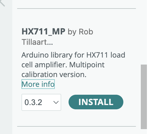
I’ve redone all the connections between the load cells, and also between the HX711 and the ESP32, but I still can’t figure out what’s going on. I’ll also share the code I’m using. I’m begging for any help to get this project working.

Top Right is the A+, Botom Right E+, Botom Left A-, Top Left E-

I've tried to power the sistem with a apple charger and the usb port from my laptop.

It is my first project, plz hope u understand.

If you need any additional information, photos, or anything else, just let me know and I’ll be glad to share it right away.

Code: #include <HX711_ADC.h>
#include <WiFi.h>
#include <WebServer.h>

// Pinos HX711
const int DOUT_PIN = 5;
const int SCK_PIN  = 15;
HX711_ADC scale(DOUT_PIN, SCK_PIN);

// Wi-Fi
const char* ssid     = "MYWIFINAME";
const char* password = "MYWIFIPASS";

// Fator de calibração (ajuste depois)
const float calibrationFactor = 1.0;

WebServer server(80);
float currentWeight = 0;

// HTML que será servido em "/"
const char indexPage[] PROGMEM = R"rawliteral(
<!DOCTYPE html>
<html>
  <head>
    <meta charset="utf-8">
    <title>Balança em Tempo Real</title>
    <style>
      body { font-family: sans-serif; text-align: center; margin-top: 50px; }
      #weight { font-size: 4em; color: #007bff; }
    </style>
  </head>
  <body>
    <h1>Leitura da Balança</h1>
    <div id="weight">--.- g</div>
    <script>
      async function updateWeight() {
        try {
          const resp = await fetch('/reading');
          const data = await resp.json();
          document.getElementById('weight').textContent = data.weight.toFixed(2) + ' g';
        } catch (e) {
          document.getElementById('weight').textContent = 'Erro';
        }
      }
      // Atualiza a cada 200 ms
      setInterval(updateWeight, 200);
      // Primeiro fetch imediato
      updateWeight();
    </script>
  </body>
</html>
)rawliteral";

void handleRoot() {
  server.send_P(200, "text/html", indexPage);
}

void handleReading() {
  // Retorna JSON com peso atual
  String json = String("{\"weight\":") + String(currentWeight, 2) + "}";
  server.send(200, "application/json", json);
}

void setup() {
  Serial.begin(115200);

  // Inicia e tara a balança
  scale.begin();
  Serial.println("Tareando sensor...");
  delay(2000);
  scale.start(2000, true);
  Serial.println("Tare feita!");

  // Conecta Wi-Fi
  Serial.print("Conectando a ");
  Serial.print(ssid);
  WiFi.begin(ssid, password);
  while (WiFi.status() != WL_CONNECTED) {
    delay(500);
    Serial.print(".");
  }
  Serial.printf("\nConectado! IP: %s\n", WiFi.localIP().toString().c_str());

  // Rotas
  server.on("/", HTTP_GET, handleRoot);
  server.on("/reading", HTTP_GET, handleReading);
  server.begin();
}

void loop() {
  // Atualiza o sensor
  scale.update();
  // Obtém leitura bruta e aplica fator de calibração
  currentWeight = scale.getData() / calibrationFactor;

  // Atende clientes web
  server.handleClient();
}
1 Like

I Dont know why, but the images didnt get uploaded

Balança-em-Tempo-Real-e-mais-11-páginas-Perfil-1-—-Microsoft_-Edge-2025-07-08-21-13-43

1 Like

Why 4 load cells? One is all you normally need. Start with the most applicable sample sketch and go from there. In your case either kitchen scale or grocery scale.

1 Like

Hey there, sorry to reply on her behalf. I’m working on this project together with the OP. We’re using 4 load cells because we’re building a low-cost weighing platform. The platform itself is made from a pallet, with one load cell at each corner. The items we’ll be weighing can go up to 150 kg, so we went with four 50 kg load cells.


Those photos are of no help. A photo of a hand drawn wiring diagram is acceptable.

I built a scale with one load cell. I have no idea how you will calibrate and tare 4 at the same time. You may benefit from using this library

and here is the doc'n link https://github.com/RobTillaart/HX711_MP

1 Like

Explain that.

1 Like

They look like three-wire half-bridge load cells with two strain-gauges per cell. If you carefully wire them up in a ring, you can have two strain gauges that constructively sum the strains in each leg of a wheatstone bridge between the half-bridge cell's center tap wire:

Where Gx represents half-bridge 'x', and nodes labeled like "WhiteG1.G4" represent the white leads from gauges 1 & 4. And the two resistors between the "BlackG1.G2", "G1Red" and "WhiteG1.G2" represent the two strain gauges in the G1-half-bridge. As per https://electronics.stackexchange.com/questions/102164/3-wire-load-cells-and-wheatstone-bridges-from-a-bathroom-scale/199470#199470

The resistances look OK as far as the 3-digit resolution goes, but the HX711 load cell amplifier needs much more precision. Each leg of the resultant Wheatstone bridge ends up with about 0.98K+0.98K=1.97K ohms in it, and the bridge needs to be balanced well within 0.020V/50V=0.4% or 2000*0.004=8 ohms. Instead of measurining kilo-ohms, try the millivolt range on your DMM and check that the A+/A- voltage is well within the +/-20mV range that the HX711 A channel needs so that "tare" will work properly.

Did you try the calibration sketch fron the library?

2 Likes

That HX711 board is 5volt-only.
The ESP32 is 3.3volt logic.
How are you going to solve that.
Leo..

1 Like

the HX711 data sheet states
Operation supply voltage range: 2.6 ~ 5.5V

I have used the HX711 on an ESP32 without problems

2 Likes
scale.update();
  // Obtém leitura bruta e aplica fator de calibração
  currentWeight = scale.getData() / calibrationFactor;

I use the same library as you with an HX711 bridge with 4 cells wired into the bridge arrangement. The reading routine is best coded to use a conditional and read the data if it is refreshed and available.

if(scale.update())
{
   currentWeight = scale.getData() / calibrationFactor;
}
1 Like

What do you mean?
All zero, all maximum, too high, too low?

Looks like you have some very bad solder joints.
Did you solder this yourself?
That would cause crazy fluctuating reading.

1 Like

Hi,

Can you please post a copy of your circuit, a picture of a hand drawn circuit in jpg, png?
Hand drawn and photographed is perfectly acceptable.
Please include ALL hardware, power supplies, component names and pin labels.

Show each load cell and label the wire colours.

Thanks.. Tom.... :smiley: :+1: :coffee: :australia:

1 Like

Some of those green boards have a manufacturing defect,
where E- is not connected to ground because of a missing ground plane.
The cure is to solder a short wire between E- and GND across the board.

OP should have used a Sparkfun HX711 board, which is designed for a 3.3volt processor.

The only option with this board is to power it with 5volt from the USB pin of the ESP32 and drop it's 5volt data signal with a voltage divider to 3.3volt. Not doing so could damage the ESP pin.
Leo..

1 Like

Hi, thank you very much for the tips! I'll try what you suggested as soon as I get home, since I can only work on the project outside of my work hours.

Regarding calibration, I didn’t do any at first — my idea was to create a calibration curve and turn it into a formula, so it could work whether I’m calibrating with a small or a large mass.

Do you recommend doing a simple calibration just to see what kind of readings I get? I didn’t even try because the variation shown by the system was very large (as you can see in the GIF).

Hi Wawa, Well, that might be a problem. My ESP32 has a 5V pin, so I just assumed it was a 5V output. So it doesn’t actually work that way?

Just to respond to your other post as well — I’m actually considering getting a different HX711. We decided not to use the SparkFun version because the goal of the project is to develop a low-cost weighing platform. Since it’s meant for inventory control, we ended up going with the cheapest option.

Hi Jim-p, I’m attaching the GIF in this reply that shows the reading variation. It goes negative, fluctuating from around -41xxxxx to -37xxxxx.

This was my first time soldering, and I still don’t understand how you all manage to get good solder joints. With the ESP32, I actually had to pay someone to do it for me because I couldn’t get it right — the solder just wouldn’t stick to the metal pads on the HX711, it would only stay on the pins.

Balança-em-Tempo-Real-e-mais-11-páginas-Perfil-1-—-Microsoft_-Edge-2025-07-08-21-13-43

Well I do believe it is the problem.
The easiest solder to use is leaded solder not lead-free.
Can you buy leaded solder where you live.

1 Like

Hi Tom, excellent — here’s the image showing the exact connections we’re following.

I can and will buy it, and I’m also going to order another HX711 just in case this one is faulty!

Perguntar ao ChatGPT

Make sure it has a rosin core.
It's not as dangerous as they make it out to be if you are just doing hand soldering. Just use a small fan to blow away the smoke.