Arduino clicking noise and resetting trying to power motor

I'm trying to build a quadcopter with 3.7v coreless motors and an Arduino Pro Mini as the controller.

When a motor is plugged in to the output controlled by pin 9 (all details below), it spins up as expected. When any other motor is connected to any other pin, the board makes a clicking noise, and what I presume to be the LED connected to SCK flashes, and the board resets.

Power is being delivered to all the output plugs as intended, checked with a multimeter. Additionally, if I plug in the motor on the other pins after the transistor is turned on (ie. reached the loop() section of the code), it sometimes briefly spins before resetting again.

It'll be great if anyone could help identify where the ticking noise comes from mechanically, and what my mistakes are to get here. Thanks!

video of clicking noise (motor plugged into output controlled by D3 in this case):

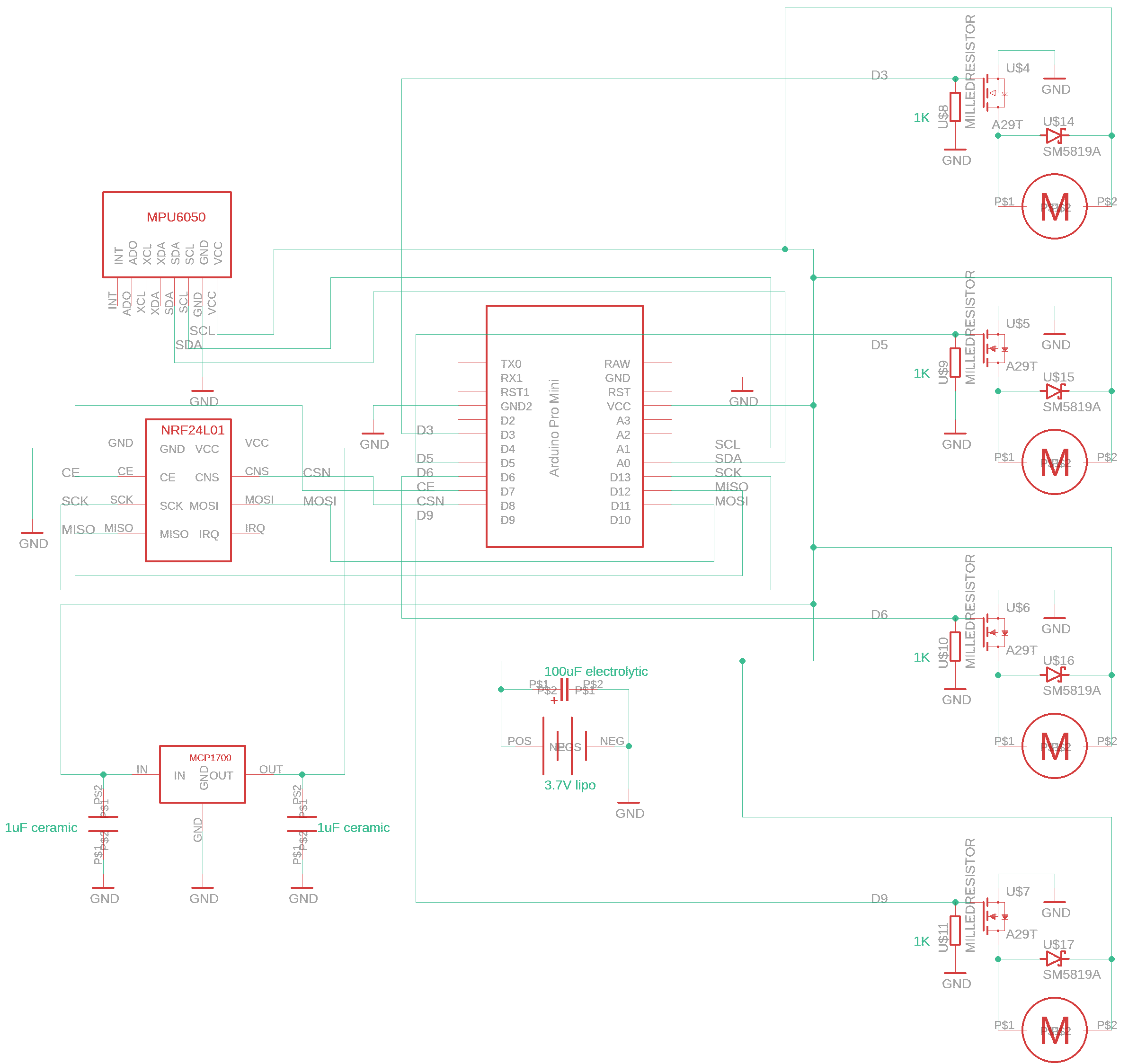
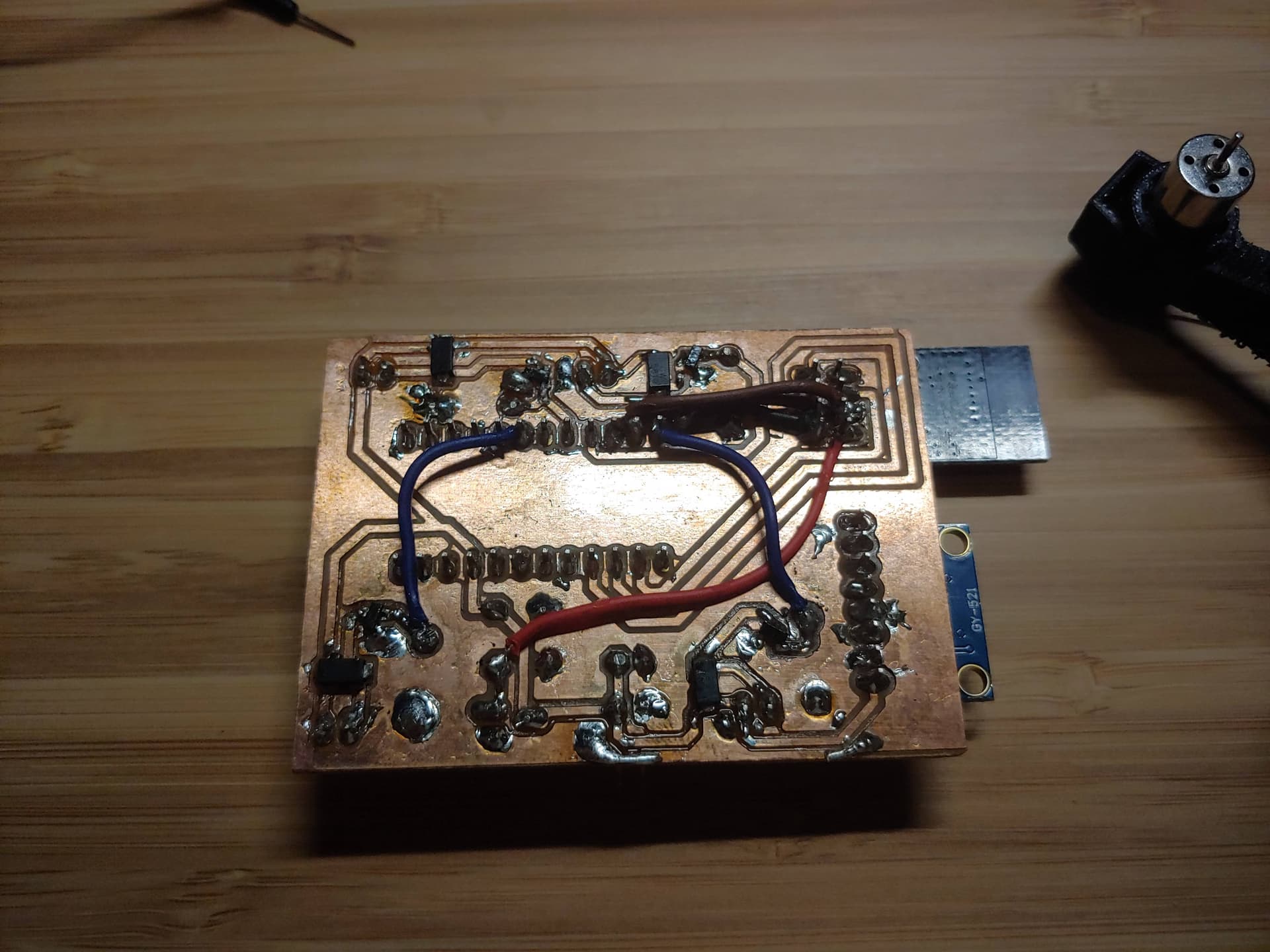
schematic is below, milled onto a single sided PCB with some hand wiring.

PCB layout below, red is milled traces and yellow/beige are hand wired (some connections look unconnected on the diagram, but there's a copper pour ground among the entire board) - note I labelled the footprint of the A29T mosfets wrong and had to flip them upside down to mount on the board, but they still all work.

testing it with this code, have also tried digitalWrite(pin, HIGH):

void setup() {
pinMode(5, OUTPUT);
pinMode(6, OUTPUT);
pinMode(3, OUTPUT);
pinMode(9, OUTPUT);
delay(10000);
}

void loop() {
analogWrite(3, 200);
analogWrite(5, 200);
analogWrite(6, 200);
analogWrite(9, 200);
}

How is the project powered ?

It's powered by a 3.7v li-po battery. Arduino (pro mini 5v 16mhz) takes it directly unregulated through VCC

You are most likely observing the effect of brownouts in the power supply. Power the motors separately from the Arduino, or use effective power supply decoupling.

Thanks, that makes sense.
I've got a 100uF electrolytic cap close to the battery and 1uF ceramic caps either side of the LDO, what would you recommend changing here?

Hi,
Can you please post a connected schematic with all wire connected and power supplies included.
Your schematic is good for a PCB manufacturer but almost hopeless when trouble shooting.

Sorry but I do troubleshooting electronics for a profession and net type diagrams do not show signal flow.

How have you got the MPU connected in the circuit?
As an example the MPU has SDA, SCL, XDL, XDA, and Int but there is no reference to what is connected to the ProMini.
3V3 and GND nets are fine but the battery voltage is not given.

Tom.... :smiley: :+1: :coffee: :australia:

Hi Tom, I hope this is what you meant - sorry if it's a little messy.

3.7volt is below the minimum recommended voltage of a 16Mhz ProMini.
An 8Mhz board would have been a better choice.
Leo..

The power distribution traces look a bit skinny for high current. A wide trace round the pcb periphery could bolster that.. These motors can pull several amps each under load.

Make sure your high current wiring isn't shared with the supply to the processor - run both independently from the incoming connector. Is your ground plane robust (this is a single layer board? Can be tricky to maintain good low inductance continuity of a ground place with single layer unless you add extra wire-links to cross-link the patches.

At these current levels 100µF is fairly puny decoupling. Try adding 1,000µF temporarily see if it helps.

Thanks for the reply.
I realised that the only output that would consistently spin up the motor is the one closest to the power supply, so the problem probably has to do with the poor pcb design and noise.
I'll take in your recommendations and will probably bolster the motor traces with some manual hand wiring, separate the power supply to the arduino and change out the cap.

This topic was automatically closed 180 days after the last reply. New replies are no longer allowed.