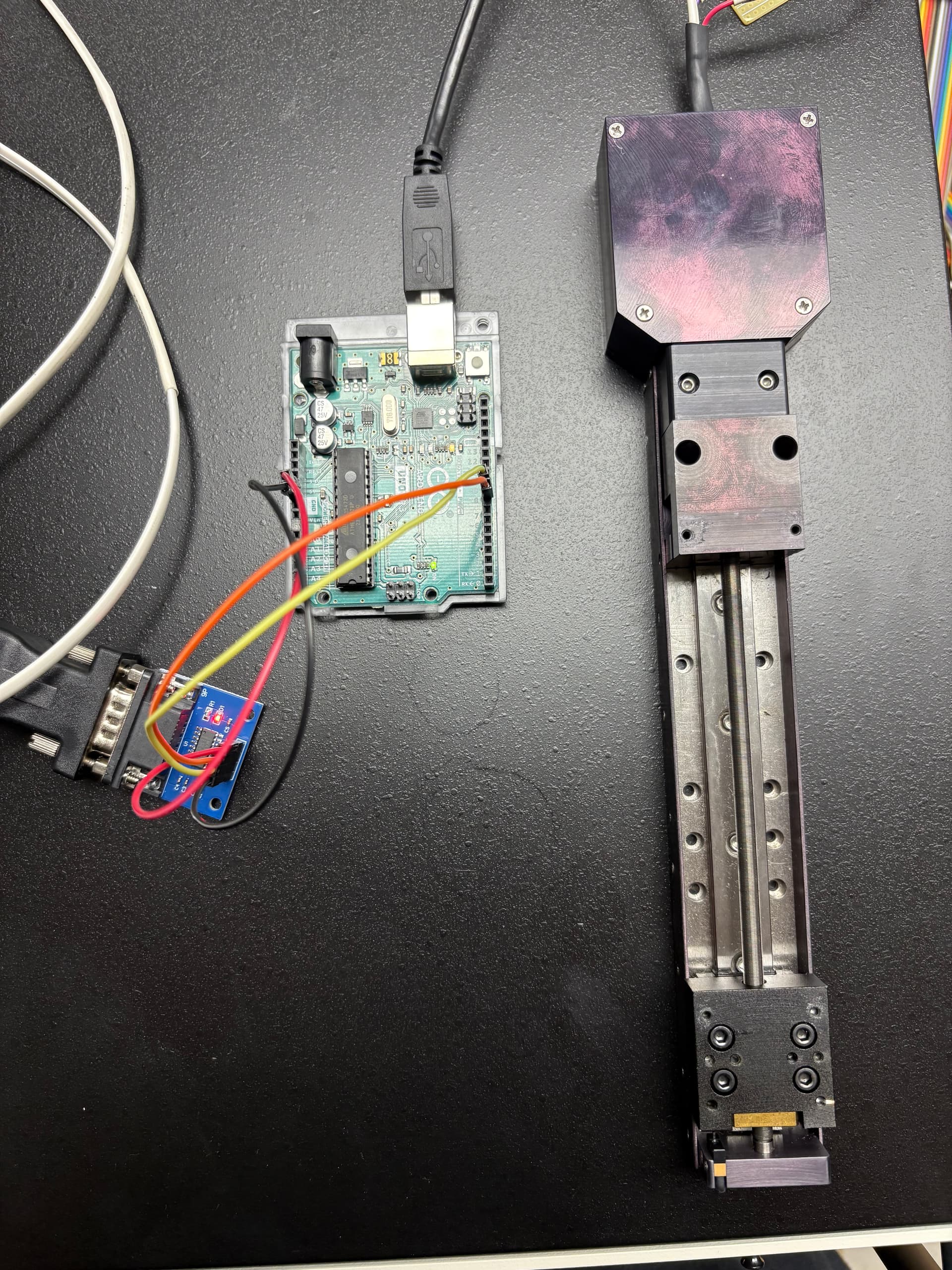
Hi all, I'm relatively new to arduino, and I'm trying to figure out how to set up a connection between an Arduino UNOR3 and an Ozoptics motorized optical delay line which takes RS232 commands. As of now, I have a DB-9 cable directly connected to the delay line connected to the arduino through a MAX232 level converter. The converter is directly powered by the arduino's built in power pins, and the RX & TX outputs from the converter connected to digital pins 8 & 9, respectively. As of now, I just want to confirm successful connection between the device and arduino. I know that the device outputs a "Ready" message upon powering up, and I'm trying to read that, but I'm even struggling with that. Any advice?
Let me know if any pictures or more information is desired, thank you so much.
For some reason i'm not allowed to upload attachments as a new user, but if you go to this link:
The above is the products list for the manufacturer, Ozoptics.
You can ctrl-f the following, "ODL-650-330PS", to find the specific part, and there is an option to download the datasheet pdf right next to it. It is password-protected, and all you need to do is call customer service for it, they don't require any screening to obtain it. To save you the time, the password is "ozcustomer". Attached is also some pictures of the setup. As for code, I don't have anything concrete, I've (somewhat desperately) been trying everything. Honestly, I'm looking for some starter code from you guys if possible to get me somewhere. Nothing I have tried gives any sensible result, other than confirming that the arduino and the ttl converter correctly reads and writes through the tx and rx pins. Thank you again.
As far as I know I am, the RS-232 pins are all being connected through the DB9 cable, but if it's better to disassemble it and work with the pins directly, I can definitely do that.
I'm not sure where to find this exact information. I've provided some pictures of the setup, but if that's not helpful please let me know. I know that the TTL converter is correctly powered, which is the only thing being powered by the arduino. The device I'm working with is separately powered. The arduino pinout is attached, the power pins are located on the left side of the board, towards the middle.
I apologize, I'm slightly confused on what you mean here. How can i set the control pins to the right signal levels? If that means baud rate, it is in fact compatible with the device, specifically at 9600.
Does that mean you removed the DB9 cable from the RS232 module, connected pins 2&3 of the DB9 connector on the RS232 module together, then confirmed that you can receive whatever characters you send to the RS232 module?
Have a look at the RS-232 and the device data sheet about the expected signals. if the device sends something ("Hello") then don't touch the control signals any more.
I did not verify each pin on the connector, I just have the DB9 port directly connected to the ttl converter. How can i go about checking the individual pins?
Yes, I would likely use a voltmeter, but what outputs should i be looking for on the pins? I'm reading about signal levels, should I be looking for voltage values outside of the range [-3, 3] V, with negative voltages, indicating a logical 1, and positive indicating a logical 0?
I'm not sure about the device itself but I don't see why the cable wouldn't be open to it. There is no mention of handshaking in the datasheet for the device at least. I will try swapping those connections.