I have an arduino controlling a ULN2003 to operate a relay which flashes a 12V bulb. The arduino 5V is stepped down by using a Traco power TSR1 from a 12V battery with the recommended filter from Traco. The relay that operates the bulb requires a GND input from the ULN2003 to operate the relay coil with the other side of the relay coil going to 12V. COMM of the ULN is also connected to this 12V as well as the main 12V for the bulb itself. I have a momentary button connected to GND for arduino input. This works great and as it should until an independent relay and button using the same 12V source and GND interrupts the arduino. The light bulb will either remain on or remain off and the arduino program no longer works. The independent relay does the same to the arduino whether inductive or resistive load. Any guidance will be much appreciated.
Post a wiring diagram showing all cimpinents used.
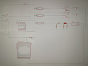
Sorry that mess of rectangles of unknown function and line mazes is not helpful ![]()
Better draw a Gnd line at the bottom, supply on top and standard symbols for all components (switches, coils, amplifiers...) in between. IC only with used pins, Vcc on top, Gnd on bottom, inputs left and outputs right. All used pins with readable labels. Often a manual drawing is clearer and easier to do than with a stupid tool.
Ive supplied the arduino with USB 5V independent of the Traco TSR1 with the same issue. Its the switching of the other relay that appears to be affecting the program. The reset button on the arduino will rectify it once this happens. The only common i can see between them is GND
The circuit layout was done using eagle as its the only tool i have apart from putting pen to paper.
Thanks but on my Pc the picture is quite unsharp and not possible to read.
Does the trouble occur when the relay coil is deactivated? In that case I suspect You need to add kick back diodes to the coils.
The ULN has flyback diodes built in, but the independent relay does not on the coil. Belt and Braces i fitted diodes to both with the same problem. Cold it be a physical thing as the arduino is around 20mm from the relay and 12v bus? Could that affect it?
Hi,
The circuit layout was done using eagle as its the only tool i have apart from putting pen to paper.
Please do.
A copy of your code will help to.
Thanks.. Tom... ![]()
Looks like you did your best to get a cleanly filtered power into the regulator, but you forgot the very important capacitor on the output. Otherwise as far as I can tell the circuit is OK.
But next time please make a proper printscreen, or export the image from your image editor, and then post it as attachment to your post in the forum. A photo of the screen (the reflection of what looks like a window on the left of the image gives that away) is generally not a good idea, even though this one came out quite well.
Thank you for the replies so far. I removed the arduino onto a test board to eliminate certain parts 1 at a time. I've isolated the issue down to the input wire to the arduino. As mentioned this requires a ground to activate and is pulled 5V high using a 4.7k resistor. The independent bulb relay coil also requires a ground to activate from a momentary button. The leads are very long from the switch to the arduino and independent relay around 2 metres and both wires are bundles next to each other. There is interference from one to the other when the independent relay button contacts. Whether i turn independent build relay on or off either can either stop the arduino program or activate/deactivate it as if I've pushed the arduino input button itself. So i think i need some sort of filter for the input to the arduino. Has anyone experienced this before or can help with an example that could work for me? Thanks
Use twisted pair or shielded cables for all signals.
We definitely need some photos - and a diagram - to figure out what you are really doing.
It goes without saying that you need to keep the controlled wiring to the relay contacts bundled and entirely separate from the bundled Arduino wiring controlling the relays, but it is not obvious from your word description.
Hi,
I've isolated the issue down to the input wire to the arduino. As mentioned this requires a ground to activate and is pulled 5V high using a 4.7k resistor.
How long are the input wires?
Are they near any other wires that carry AC or any significant current?
Thanks.. Tom.. ![]()
Kiwi:
The leads are very long from the switch to the arduino and independent relay around 2 metres and both wires are bundles next to each other.
Bundled wires create a very tight electromagnetic and capacitive coupling. It is many times stronger than someone assumes who is not familiar with it. When a ground wire is influenced, then it is even worse. Grounding is a craftsmanship on its own.
An extra flyback diode at the relay itself is always good. You still will have some current and voltage peaks though.
Suppose there is a ground current of 1A, and there are two wires for the ground. One thick wire and one thin wire. Everyone would assume that most current will flow through the thick wire. However, if the thin wire has a tight coupling with the wire that supplies the power, then the ground current can decide to go through the thin wire.
The solution has already be mentioned by others. But there is more than you can do.
- use a seperate (shielded) cable for the switch
- use seperate GNDs for power and for sensors/inputs/switches. Do not connect the switch GND to the power GND. See them as two seperate circuits. The switch GND should be connected to the Arduino board, not halfway to something else.
- lower the resistor from 4k7. For example 470Ω or 1k.
- perhaps a optocoupler can be used for the switch if it is hard to seperate both circuits. When done right, a optocoupler will solve all problems at once.
The electromagnetic coupling can be used as an advantage.
The Cat5 and Cat6 cables have a number of two wires wrapped around each other. Those twisted pair wires can be used for a signal to travel 100 meters. That is possible because of the tight electromagnetic coupling.
I have a momentary button connected to GND for arduino input. This works great and as it should until an independent relay and button using the same 12V source and GND interrupts the arduino. The light bulb will either remain on or remain off and the arduino program no longer works. The independent relay does the same to the arduino whether inductive or resistive load. Any guidance will be much appreciated.
The problem is due to having no flyback diode across this relay coil. The other relay is OK because the ULN2003A has an internal diode.
This topic was automatically closed 120 days after the last reply. New replies are no longer allowed.