Yes, that would be a good start without damaging the board! If that doesn't help, then you can always proceed with isolating the supply of the 328P itself to see if there's an interaction with other devices on the same 5V supply when the relays switch.
Ok so I have remove the K3 relay and there is the same problem, when I turned off relay that is connected to battery relay, the board restart….
OK, so I have use an oscilloscope when i turn off relay on board connected to relay of battery, a signal happend and all reset
this is a 5V pulse perturbation
It tests if the problem is an inductive pulse on the MCU power supply.
You might try replacing the 4.7uF (C8) with a 470uF or greater capacitor.
This will absorb most of the inductive pulse.
As the 5v relays are not tripping the MCU then increasing the 5v power supply filter capacitor may fix it for the 12v relays (which may have more inductive power).
You do have another benign problem. Your 5v power supply filter is not good enough to prevent your K3 relay contact bounce from causing multiple resets of your MCU.
Regards Alan
Hello, thank you for your answer.
If I understand correctly there is therefore a pulse when the relay disconnects due to the inductive load connected to 12V
So if I modify C8 the problem is that only the MCU will be protected, the other components (Chip can, ...) may be disturbed right?
Can i add a capacitor in K3 relay 5V out ? for all 5V distributed
Is there a solution for the optocoupler as well, should I remove it (because same 5V power supply) or can I split the 5V in two?
Still on the relays, I saw that some were using an RC filter in parallel with the load (https://europe1.discourse-cdn.com/arduino/original/4X/0/b/6/0b61ea81375ed7dabc4f296c006fcc77238d0b68.png) in in my case it may be complicated to set up ...
Finally for the K3 relay, you talk about the fact that when the contact is triggered, it resets the MCU because for a few milliseconds there is no more 5V? if this is indeed I know, I have not found a way to counter my problem: I have 3 5V power supplies, one for the ICSP connector, one via the USB port and one via the 12V, I have put diodes for the USB and ICSP but the 12V one I did not know how to do
I was trying to avoid getting into design issues/strategies, which is why I proposed a solution to your current problem.
My thoughts were that the inductive power for the 5v relays were not enough to generate a MCU trip but the 12V relays were. Therefore adding the extra capacitance to the MCU power supply filter could fix the problem and the solution would be an easy fix as well.
So the question is how does a relay with a back-EMF diode trip the power supply? The answer is that the relay coil must be under-damped and the "reverse" voltage swing/undershoot pulls down the power supply. So lets us look at the 12v power supply and ask the question, is the design susceptible? We only have a 0.1uF and 0.33uF capacitor on the output to absorb the negative inductive pulse, not much. Now if the input to the 5v regulator can be pulled down then it would brown-out the MCU. So it is a possible theory. In the absence of any test measurements, this can only be a theory.
Okay, so how can we fix it? Put a big 4700uF capacitor on the 12v power supply line. Okay, may be something smaller will work just as well!
Those extra components are the snubbing circuit mentioned by Grumpy_Mike. Basically they absorb high frequency noise/oscillation and dampen the coil (preventing the undershoot). It is the basically the same issue as we talking about right now.
If you know the inductance/capacitance/resistance of the relay coil then we can design a perfect snubber circuit, but basically all we need to do is dampen the coil.
I really hate your power supply design so best I not say anything, regards Alan0
Ok si I understand...
Relays that I use are IM03DGR : https://www.mouser.fr/datasheet/2/418/ENG_SS_108-98001_S[1]-1210543.pdf
So I'm going to replace the 0.1uF capacitor (C3 and C9) by a 4700uF to absorb oscillation...
Why is my power supply design is so bad? I tried to do the same thing as on the arduino but with a 12V power supply in addition ...
If I can also solve this problem or improve the reliability of the power supply ....
I am kidding about the 4700uF! Try the 470uF first.
No I can't go off on your power supply design because the "White Coats" may come looking for me! And I have not seen the full schematic and scope of the project.
If you get to test your relays with an oscilloscope and can confirm that your problem is an inductive spike, then we could look at other measures. The capacitor is simple to implement and may work.
Regards Alan
I tested with an oscilloscope already,
We agree, the relay coil is supplied with 5V, and the 12V passes from the power supply of the card, through the relay, to the remote load.
When the relay is deactivated, the 12V which passes from the card to the remote load remains very smooth.
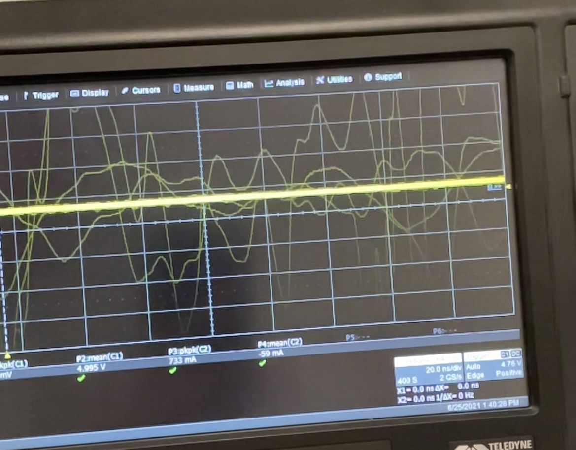
On the other hand, the 5V oscillates (several oscillation like waves) then it is restored
For the scope of the project, my goal is for it to be industrial, and the diagram I can send it to you privately if you want.
I really thank you for helping me, I am not an expert in electronics I learned everything in the "field" I am mainly a coder
Really? 
What you are trying to say is that the power supply over-corrects. Once the device - whatever it is - switching the relay turns off, the back-EMF of the relay has no effect whatsoever on the power supply, whatever it does.
But part of the general problem here is failing to understand that the transient occurs in a loop comprising the power supply, the relay in parallel with the commutation diode, and the switching device. It is current transients in this loop which are inductively coupled to other parts of the circuit, so it is critical to make this loop as physically small as possible by locating that 470 µF capacitor adjacent to the switching device and the commutation diode.
The proximity of the relay itself is actually not quite as relevant since its inductance is actually preventing sudden changes in the current flowing through it.
Okay,
I have no suggestions for you.
Regards Alan
so basically, either I place a capacitor of 470uF upstream of the 5V distributed to all the relay circuit.
Or I put a second 5V regulator which only takes care of the relay part (at right of the optocoupler) and I also put this capacitor ?
UPDATE : I have change C8 by a 47uF capacitor and C9 by a 220 (i don't have 470uF and i can't change the board because it's a PCB) but nothing good, the board crash and restart
Update 2 : I have add a 220uF capacitor in parrallel with C8 47uF but same thing
This is what I have when relay switch off
For the power supply ?
Hi,
Back at post #10, you said "ALL the tracks are 0.750" 0.75 what.
Does that include the most important part of a PCB, your GND?
Are ALL your gnd tracks between integrated circuits 0.75?
If so, you are asking for trouble.
Can you connect the gnd clip of your scope probe to GND where your power comes in and connect the probe tip to a gnd track at the farthest end of your PCB.
Then got through activating your relays.
Please state with each trace you post;
Where you connected the probe gnd.
Where you connected the probe tip.
What is the horizontal sweep rate selected.
What is the vertical volts/cm.
Is your input selected AC or DC.
Is your probe set on by 1 or 10.
Can you PLEASE post a jpg of the top and bottom traces of your PCB, not the component laden image that you have posted in post #10.
Your CAD should be able to EXPORT jpg images from the PCB track editor.
Thanks.. Tom... 


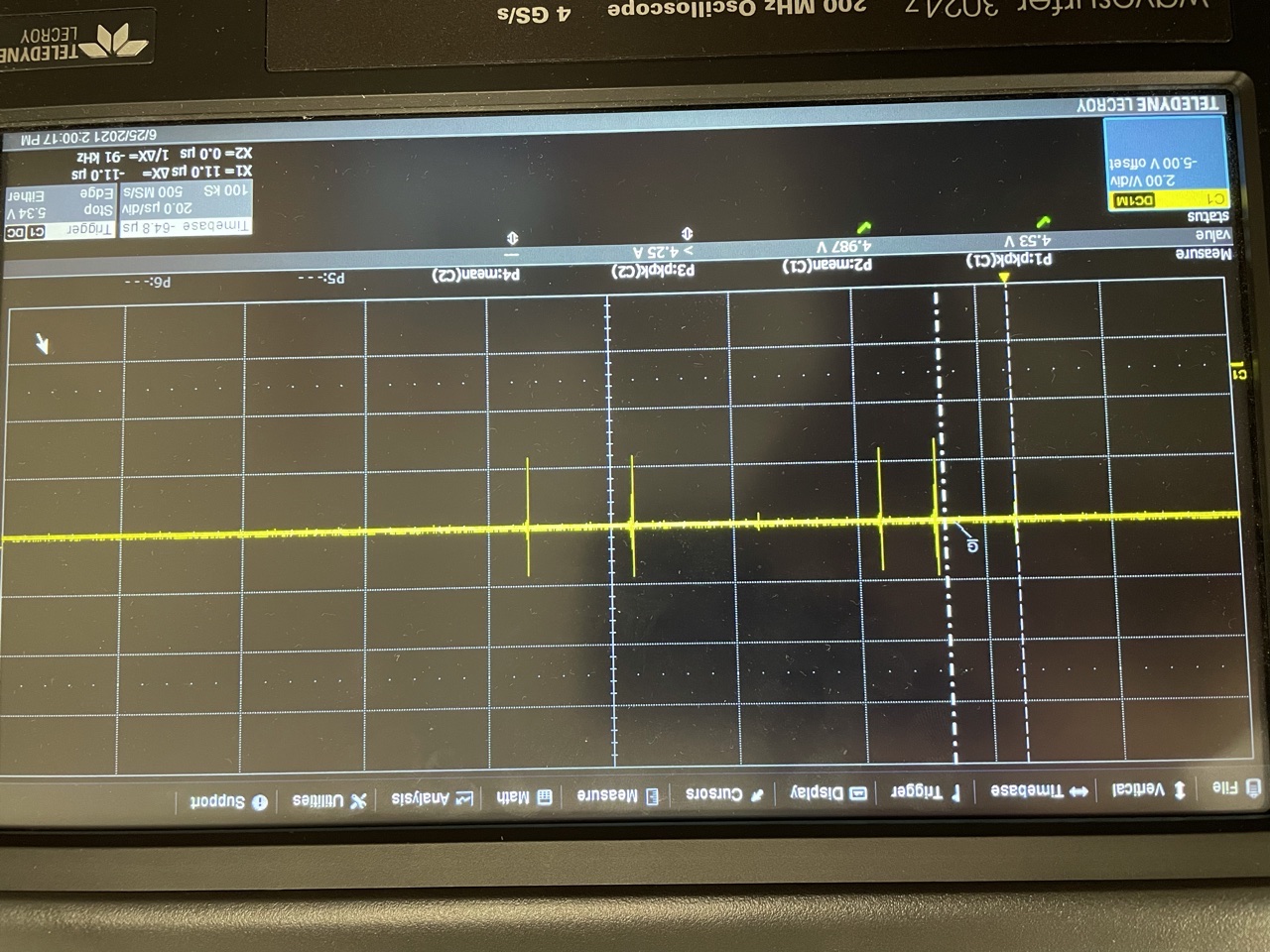
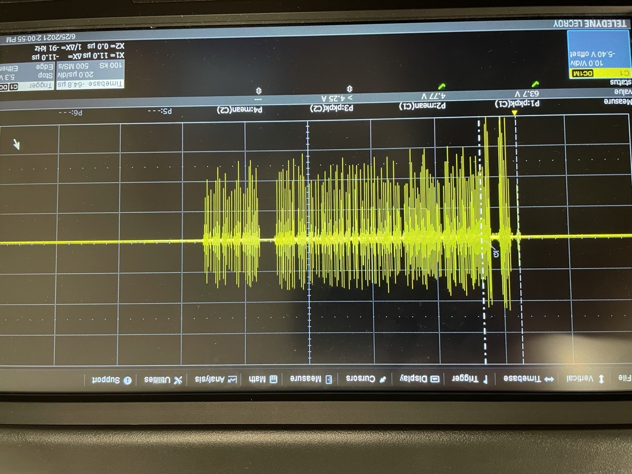
Hi, have you seen my previous post? I put the 5V signal when I activate and deactivate the relays.
In addition, the ground of the remote relays (in the battery) are on the same ground as my board...
I will see what I can do but I will not be able to use the oscilloscope before Monday ... In the meantime here is the image of the tracks


Do not replace the 0.1uF capacitor with anything, add the larger one in parallel. There is a lot more to this than simply the overall capacitor value.
A 470uF has a lot of inductance and so is not very good at suppressing high frequencies. The 0.1uF should be a ceramic type, these are good at suppressing high frequencies, so it is very common to use a big and small capacitor in parallel.
This link discusses this aspect in greater detail.
http://www.thebox.myzen.co.uk/Tutorial/De-coupling.html
Hi,
This may help with respect to types of capacitors and their uses;
https://www.jameco.com/Jameco/workshop/ProductNews/identifying-caps.html
Tom.... 
I read 10v/div and 20us/div.
Total period about 1ms, this look like relay bounce.
Frequency about 1MHz.
Voltage about 40v peak to peak.
Looks like the relay does not have diode protection (or the diode has failed).
My "two cents", Alan
Hi,
Can you please post the specs of the "other" relays that your PCB relays are activating?
Are the "other" relays AC or DC coils?
Do you have the 12V relay supply wires ANYWHERE near the other lower voltage and signal/ control wires?
Can you please post a picture(s) of your project setup, so we can see your component layout?
Tom...
Thanks.. Tom...