I have a square d pressure switch to control some pumps. I have flow sensors on the pumps that tell me when liquid is flowing.
I want to detect if 120v ac is present on the pump power wires. This way I can tell, liquid should be flowing if not shut down that pump.
I already have my punps on relays but they are only to shutdown the pump. I know there's multiple ways to do this. Im trying to avoid optocouplers.
thought about making a ac voltage divider to bring the voltage down to 1.1vac but im concerned of transients and flyback voltage could exceeded 5v even through a divider and frying my pin.
thought about connecting a 120vac to 5vdc psu to the power wires for the pumps. The 5vdc powersupply would be powered when the pump is on.
Using a split core current sensor to detect when current is flowing through a wire, do they make a current sensor that can be wrapped around multiple wires? Like netural/gnd/com all at once and still tell there is voltage/current present on the wire?
I use splitcore sensors in my breaker boxes with electricity meters but not with aruduino. So I'm not sure what to expect, same transient/emf spike problems? My pumps only use about 3 amps so I could use a very small splitcore current transformer. I only found as low as 20a though
How do those contact less voltage detectors /testers work?
I'm here in search of methods to do this Thankyou.
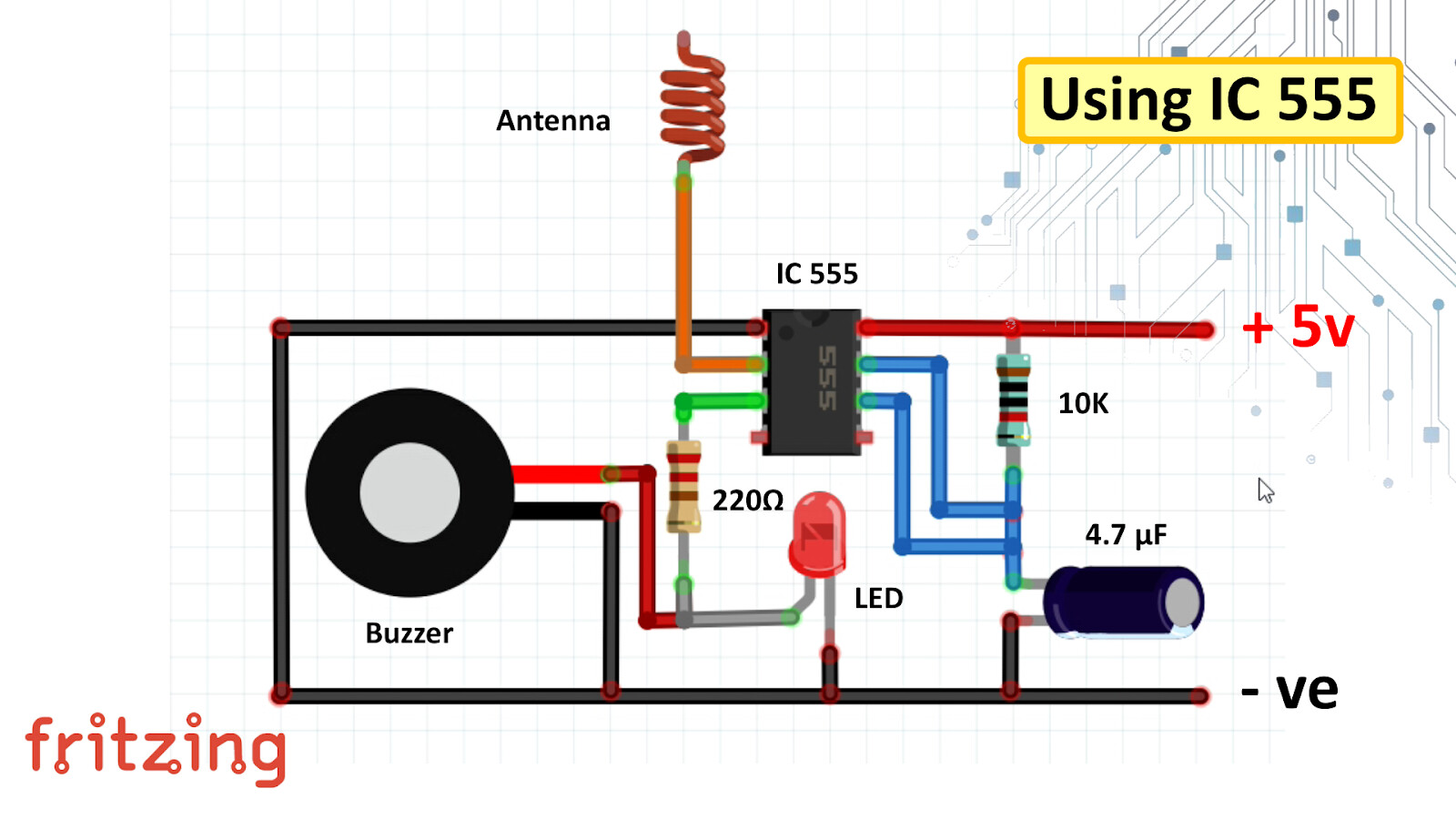
I built a non contact voltage sensor with the 555 timer, it seems to work but how can i adjust the sensitivity of the circuit? seems just a little over sensitive. i just use the led no buzzer
The antenna is on the trigger pin, from what i read trigger must be pulled low to activate trigger. I want to replace the led with arduino Input, How is the cap affecting the circuit? do i need the cap if i dont need the output signal to the led to pulse? wont the signal pulse without the cap since ac +120v then -120v?
No! The Arduino must be electrically isolated from the lethal voltages. It also has to be isolated from you, and your computer when there's a USB connection, etc. It's dangerous and a violation of electrical codes.
Also, the AC would have to be rectified because the Arduino can be damaged by negative voltages.
Yes, that is a common solution and probably the simplest.
No, the current is moving in opposite directions through hot & neutral and the magnetic fileds cancel.
Another fairly-easy solution is a relay with an AC coil. Then you can just use the Arduino's built-in pull-up resistor on the contact-side (with the other contact connected to the Arduino's ground).
I don't actually know. It's probably capacitive (with a high-gain amplifier).
...Magnetic/inductive pick-up requires current so a coil or hall-effect sensor wouldn't detect anything when no current is flowing, and again you have the cancelation problem when current is flowing. That's OK for you, because you'll always have current when the motors are on, but I'm pretty sure those voltage probes work with no current.
I just learned recently that there is in fact electrical code for low voltage devices in houses. Doorbells, switches, alarms, etc. In USA i think it has to be CL2 or CL3 rated cable to go in a wall. Off topic but yeah..
I know the voltages from AC voltage divider would have to be rectified for Arduino and im not bringing a 120v line to the Arduino, i would make the divider at the square d switch, but it just sounds like a bad idea and the possibility to destroy my Arduino.
I'm kind of liking the idea of this capacitive? 555 timer voltage detector. seems safer, galvanically isolated from the HV source and easy to build. But can i get away without the 4.7 uF cap? i would just send a high/low logic signal from the 555 to the Arduino input pin with a current limiting resistor so i don't care if the output pulses or not. I actually prefer it not to
The 555 timer detects presence of voltage regardless if current is flowing so that nice too.. How can i adjust the sensitivity of the circuit in post 2? Im not sure of the purpose for the 10k resistor
EDIT:I tried using a 900k ohm resistor between trig and antenna but it didn't seem to change anything. My overhead fluorescent lamp triggers it. My antenna is a 28gua 4 inch wire. I think placement of components can have a affect on things BUT there must be a way to change the sensitivity.
Do you have any idea how hot these neon indicators get? im looking at 110v 0.067w neons indicators but im not sure what temp they typically run at when running lower-ish brightness. I ask because im thinking about how im going to house them. Want to make sure i can 3d print some type of enclosure for them and the LDR
Just remember if you go the neon bulb route that when the neon gas ionizes at its threshold the neon lamp becomes pretty much a short circuit. Place a resistor in series with the bulb to limit the current or just buy a neon bulb with series resistor included.
Would this optical isolation board be able to handle transients? the 5.1v? Zener would protect from relay contacts/flyback emf? I know the neon bulb will "handle" it.
I'm going with Paul. You have 120 VAC and there are plenty of 120 VAC opto-couplers designed specifically around what you want to do. If you are concerned with relay contacts powering your pump place a "snubber" across the relay contacts. Flyback is the result of a DC collapsing field on a DC coil relay (or the collapsing field of an inductor. Then we just place a flyback diode across the coil observing polarity.
That or build your own opto-coupler as has been described. For a few bucks (USD) I see Paul's solution as the best solution.
Im just worried about emf from the pump blowing the zener. It looks like the zener is what limits the voltage to the optocoupler but i don't have any experience with zener diodes, will the zener blow up if i dont use snubber or MOV on the High voltage in? can voltage peak on 120vac exceed 220v because of back EMF from motor coil?
OK, maybe I have this wrong but you have I believe 120 VAC 60Hz pumps. These are AC pumps not DC powered pumps. All you want to do is detect if AC voltage (120 VAC 60 Hz) is being dupplied to the pump(s). You have pressure and flow sensors in your scheme. You can detect voltage to a pump or current to a pump or both. You are using relays apparently to turn the pumps On and Off. The relays are switching 120 VAC to power the pumps. If you have any concerns with relay contacts arcing you use a "snubber" consisting of a resistor & capacitor in series across the relay contacts.
How is back EMF measured on an AC motor?
You can measure the voltage and current apllied to the motor, and subtract the I*R from the voltage applied, and voila you get your back EMF. I doubt back EMF is going to be a problem in any of this.
All you want is to detect if AC mains is present or not powering the motor. Off the shelf turn key solutions like an opto-coupler module will give you what you want or need. They afford isolation also. You can also use a simple 120 VAC relay across the pump line and use those contacts to feed your control system.
Thanks for that information. I think the zener diode in the optocouple board is for limiting the voltage to 5.1v and the resistor is limiting the current through the diode. This probably powers one side of the optocouple? I also see a bridge rectifier and a cap for stableizing the 5.1v
I use currently 130v 10a varistors and they are a must until I change them with TMOV
Is back EMF the wrong word for the phenomena I am describing ?
The relays connected to the pumps are normally closed. I only energize the relays to disconnect power. the pressure switch handles turning the pumps off and on
Starting from the AC in side the large resistor looks to be a 150 K Ohm 2 watt resistor. D1 is a full wave diode bridge. D2 is a Zener diode and yes, a 5.1 volt Zener. This clamps the voltage across it at 5.1 volts DC. C1 a 100 uF electrolytic cap is there as a filter. LED1 is an indicator mains voltage is present and in series with the opto coupler. The opto coupler collector output shows a 47K Ohm pullup to Vcc. My read on the module is that it is designed around a 220 VAC input. I have seen several versions of the module using different values of R1.
Also please note this topic is labeled as Solved with the Only Reply note.
Only reply here if: