I am currently using a MikroElectronika Flip n Click board and tasked with the following:
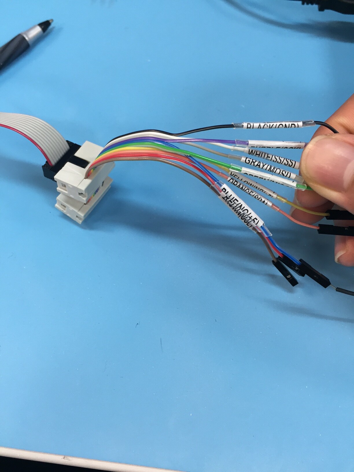
There is an existing SPI communication going on between 2 processors on a device. I have to tap into the communication between these 2 processors with a a set of wires connected to my Flip n Click board.
My goal is simply to read the SPI data that is coming being communicated between the 2 processors. After getting this data, I have to code and convert it into instructions for a CAN SPI click board. But I have issues getting the data.
The 2 processors are only engaging in 1 way communication, as the Master is sending data to the slave and whatever the slave responds is irrelevant.
Is there a simple way to use commands in the SPI.h library to just print out the data that is being transferred? I tried setting up my board as a slave to the master, but this would bring up issues since masters can only communicate to one slave, and I do not think Arduino Due supports slave mode.
My alternative is to run the board in standard master mode, with the attached device's dataline as an SPI slave. But I don't know how to read data from a constant stream slave. All of the examples I have seen online detail how to send or transfer data to an SPI slave, but I only want to constantly read data into my board. There also is not much clear documentation about how to use the Flip n Click board and its SPI features. (which pins are MOSI, MISO, how to run it on Arduino IDE)
Any SPI sample code that works on Arduino Due/Flip n Click by having the Master read incoming data from a slave, or simpler would be very helpful.
Any help as to how I can set up a simpler way of approaching this task would be helpful.
I know that the data between the 2 processors can be read simultaneously, as a colleague demonstrated that a Beagle SPI was able to connect and display all of the MOSI data.