Hi all,
I'm working on a project where I'm using an Arduino Due to communicate with various devices via SPI. Apart from the issue stated in the subject, the SPI communication to the main (writing and reading to various registers) works well. All of the SPI read/write functions are using the Arduino SPI library.
The issue I'm having is reading the output from ADS 7042 ADCs. The ADC value is used for calculating a current, which is the same current drawn from one of my power supplies (i.e. after converting the ADC value, I can see if it is equal or close to the "real" value). However, the Arduino's read hexadecimal value differs a lot from what it "should be".
I tried analyzing the signal using an oscilloscope. When probing the MISO and CLK lines, the captured data in the oscilloscope shows the correct hexadecimal value (and is not equal to what the Arduion reads). The code snippet used for reading the data via SPI:
SPI.beginTransaction(SPISettings(8000000, MSBFIRST, SPI_MODE1));
set_chipselect(pin);

for (uint8_t i = 0; i < frame_length; i++) {
    p_response[i] = SPI.transfer(0x00);
}

clear_chipselect(pin);
SPI.endTransaction();
where pin is the chipselect for the ADS 7042 (currently using two of them) and frame_length is the length of the data cycle (frame_length = 2 in this case).
I have tried changing the clk speed in SPISettings to no avail. Any ideas as of why the Arduino would interpret/read the data differently than the oscilloscope/signal analyzer? Thanks in advance.
looking at the Serial Interface Timing Diagram(figure 1) in the ADS7042 datasheet regarding the way the data is clocked out from the ADC something like this might work:
(compiles not tested!)
#include<SPI.h>

const uint8_t pin = 10;

void set_chipselect(uint8_t pin)
{
  digitalWrite(pin, LOW);
}

void clear_chipselect(uint8_t pin)
{
  digitalWrite(pin, HIGH);
}

void setup()
{
  Serial.begin(115200);

  pinMode(pin, OUTPUT);

  set_chipselect(pin);

  SPI.beginTransaction(SPISettings(8000000, MSBFIRST, SPI_MODE0));

}


void loop()
{
  uint16_t p_response = 0;

  set_chipselect(pin);

  //read ADC
  p_response = SPI.transfer(0x00); //receive upper byte (ADC bits 11-6)
  p_response = (p_response << 8) | SPI.transfer(0x00); //receive lower byte (ADC bits 5-0)
  //----------

  clear_chipselect(pin);

  //re-aligning the bits to get the correct value
  p_response = (p_response >> 2) & 0x0FFF;

  //print out received value to serial monitor
  Serial.print(p_response, HEX);
  Serial.print(", ");
  Serial.println(p_response, DEC);

  delay(1000); //arbitrary loop delay
}
hope that helps...
sherzaad:
hope that helps...
Thanks for the reply! I apologize for leaving out a lot of details, feel free to ask or point out things/information I should've included and I'll edit/update my post(s) accordingly.
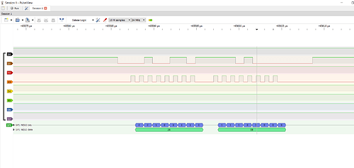
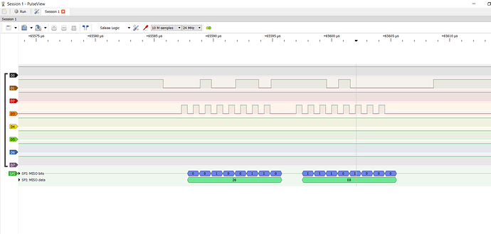
The main issue is not converting/manipulating the 12 data bits but to get the Arduino to read the bits "correctly". The result is as if the CLK is not synchronized with the MISO signal (even though the signal analyzer/oscilloscope shows that it is). E.g. here is a picture when probing the signals:
Where as the Arduino SPI read function returns a way different value (in the case in the picture I got 0x4DD0). I tested reading the SPI data by rewriting and implementing the code you wrote instead, but the issue persists. I've also tried using the SPI.transfer16() method.
I'm currently using digital pin 31, 33 for the ADC chipselects if that is of any interest. The other SPI devices are connected to 23, 25, 27, 29. The SPI MISO, CLK, MOSI, GND signals are connected to the ISCP SPI header. I also just tested my code on another setup using identical hardware, and faced the same issues (oscilloscope shows correct value, Arduino does not). To add to this, a friend of mine helped me test the ADS 7042 using Matlab with the Arduino. The Matlab application was able to read the ADC value using the same SPI settings as I am (8MHz, clock polarity = 0, clock phase = 1).
I think my next attempt to solve this will be to test another SPI library and see if anything changes.
markd833:
0x26E8 x2 = 0x4DD0
I was hoping to find some sort of relation between the Due's result and the logic analyzer's result (e.g. the results differ by a bit shift or something similar) but after doing multiple measurements there doesn't seem to be any.
I also found out that the error changes depending on what frequency I use in my SPISettings. If I set the frequency to lower than 4.2MHz, the read error will differ from the error I get when setting the frequency equal to or greater than 4.2 MHz. Not entirely sure what conclusion I'm supposed to draw from this information though...
What measurements did you get?
Can you post some of your measurements here so we may be able to try and figure out what's going on? If you have a few examples of what your LA says against what your Arduino Due says.
Are you using SPI_MODE0 or SPI_MODE1?
markd833:
What measurements did you get?
Can you post some of your measurements here so we may be able to try and figure out what's going on? If you have a few examples of what your LA says against what your Arduino Due says.
Are you using SPI_MODE0 or SPI_MODE1?
Apologies for the late reply. I've made some progress (and am also feeling very stupid right now). After seeing your question regarding which SPI_MODE I'm using, I re-read the datasheet yet again and realized that I should probably sample on the positive clock edge since the data is output on the negative edge. I should not have been neglecting this just because my friend managed to use SPI_MODE1 without any issues (and sherzaad even pointed this out, I was however only focusing on the SPI.transfer-part).
So now the remaining issue is that the converted value from the ADC is a little bit off in terms of the "real" current drawn, but that is a question for another time and forum. Thank you (and sherzaad) for the help!

