How to read adc port in code?

I need to contact the ADC via arduino nano on the SPI bus and get a response. I can send a byte, but I can't get a response. The hardware SPI did not work, I decided to write a software one, maybe I'm reading the port incorrectly? The output is just zeros.

#define rStatADC	0x10
#define rDataADC	0x11
#define rModeADC	0x12
#define rFltADC		0x13	
#define rDacADC		0x14
#define rOffADC		0x15
#define rGainADC	0x16
 #define rTestADC	0x17
 #define wModeADC	0x02	
 #define wFltADC		0x03
 #define wDacADC		0x04	
 #define wOffADC		0x05
 #define wGainADC	0x06	
 #define wTestADC	0x07
 
 
 #define spi_cs      8 // это D8  ардуино
 #define spi_do      12 // это D9  ардуино
 #define spi_di      10 // это D10 ардуино
 #define spi_clk     11 // это D11 ардуино
 
 
 // задержка
 #define SPI_time 10
 
 char Byte=0;
 
 void setup() 
 {
   Serial.begin(115200);
   pinMode(spi_clk, OUTPUT);  
   pinMode(spi_do, OUTPUT);
   pinMode(spi_di, INPUT);
   pinMode(spi_cs, OUTPUT);
   digitalWrite(spi_cs, HIGH);     
   delay(10); // ждем устаканивания питания
   //сброс
   digitalWrite(spi_cs, LOW);
   for(int i = 0; i < 32; i++)
   {
   SPI_wr(0xFF);
   }
   digitalWrite(spi_cs, HIGH);
 }
 //--- основной код----
 void loop() 
 {
   digitalWrite(spi_cs, 0);     
   SPI_wr(0x12);
   char abv = SPI_read();
   Serial.println(abv, HEX);
   // abv = SPI_read();
   // Serial.println(Byte, HEX);
   digitalWrite(spi_cs, 1); 
   delay(100); 
 }
 
 //-----передача байта в шину - Write-----
 
 void SPI_wr(char Byte) 
 {
   char i;                 // счетчик для цикла
   for (i=0; i<8; i++) 
   {   // цикл на 8 бит
     digitalWrite(spi_clk, LOW);          // тактовый спад
     //delay(SPI_time/2); // формируем половину паузы
     if (Byte & 0x80) digitalWrite(spi_di, LOW); else digitalWrite(spi_di, HIGH); // выставляем один бит
     Byte<<=1;                                 // двигаем байт 
     delay(SPI_time);    // завершаем паузу
     digitalWrite(spi_clk, HIGH);          // тактовый фронт
     delay(SPI_time);   // формируем импульс
   }
 }
 //-----прием байта ---- Read-----
 unsigned char SPI_read() 
 {
   char i, abv = 0; 
     for (i = 0; i< 8; i++)   
     {   
       delay(SPI_time);  
       digitalWrite(spi_clk, 0); 
       delay(SPI_time);
     if (digitalRead(spi_do)) 
 //      abv = abv | 1;
       abv++;
       if (i!=7)
       abv<<=1;
       digitalWrite(spi_clk, 1);  
     }
     return abv;
 }

Please clarify, what do you try to achieve? Contact ADC port via SPI?

what ADC are you using? provide a link to the datasheet ?

Hi,
Can you please provide in a new post;

  1. Link to specs/data of ADC.
  2. Schematic of your project.

Thanks.. Tom... :smiley: :+1: :coffee: :australia:

AD7730_datasheet.pdf (498,7 КБ)

Yes, ADC AD7730, The clock and writing work for me, reading does not work, I send bytes to the register, but I can’t read, apparently the read function is implemented incorrectly. But I don't know how else to make the program read the data sent to the ADC. In this example, I am trying to read register 0x12. The code should respond with the address 01B0, and there FFFFFFF.

There seems to be a growing trend here of ambiguous questions, followed by short incomplete answers.

Please that time to answer everything you are asked. If English is not your first language please write much longer answers a. Use one of the online translators.

Please cooperate with us to make it possible for us to help you. We would love to help you, but we can only know what you tell us, and guessing leads to many people wasting their time.

You don even say what sort of Arduino you have! There are many types of Nano it being just the name of a form factor rather than describing the type of system.

AD7730_datasheet.pdf (498,7 КБ)
2) Nano - AD7730
d8 - CS 19
do12 - di22
di10 - do21
clk11-sclk1

Hi, @volkodav215
This may help from another post in the forum

Google;

ad7730 arduino

Tom.. :smiley: :+1: :coffee: :australia:

If I knew a lot, I would know what to do and would not ask. For the first time I hear that there are many different arduino nanos, and what does it make sense here? It is the code that does not work, the reading function is unsigned char SPI_read (), maybe I am accessing the port incorrectly, trying to read it, - if (digitalRead (spi_do)). I ask you to look at it, I have no experience in programming, perhaps you will immediately see an error in the code.

This line will be transfer the byte inverted:

Your read function doesn't looks correct too.

Where do you find this code? Why you don't use the hardware SPI ?

hardware does not work, in response it gives out all sorts of nonsense, what you sent from above works as it should. But reading does not plow

The topic mentioned by @TomGeorge in reply #9 strongly implies that hardware SPI should work. Faced with "I can't get it to read at all", I'd put more effort in that direction. Did you do the (possibly unusual) SPI initialization?

  SPI.begin();
  SPI.setDataMode(SPI_MODE3);
  SPI.setBitOrder(MSBFIRST); 
  SPI.setClockDivider(SPI_CLOCK_DIV16);

This is not an answer to Tom asking you to supply a Schematic of your project. It is just a list of what wire connects to what between the ADC and your Nano. What it does not show is what other connections you have made to the ADC apart from these. If the answer is nothing then there is your answer.

That sounds to me what you would expect if you read the output of an ADC with nothing connected to its analogue inputs. When an input is not connected to anything, this is called a floating input. Due to the very high impedance of these inputs they will pick up all sorts of electro magnetic interference form the mains, near by wiring, and even radio waves.

This will produce a randomly fluctuating reading that you could very well describe as "all sorts of nonsense". So to get a reading of zero then connect all the ADC inputs to zero. If you want to get a reading then use a potential divider on the input pins to get the voltage you want to read. As these are very small values make sure the resistor ratio provides the correct voltage.

Points that would have been clear if you would have produced a schematic when asked for.

Another thing you need connecting to that chip is some decoupling capacitors. At least a 0.1uF between the power input and ground to that ADC chip. Here is a link describing the how and why of decoupling components. These are not optional in circuits.
http://www.thebox.myzen.co.uk/Tutorial/De-coupling.html

Now a bit of etiquette advice for this forum.
You might want to look at this How to get the best from this from this Forum before you proceed any further.

It will tell you how to post code correctly, I don't know what you are doing at the moment but all lines of code you post start with a > which is useless.

This is because even if we wanted to copy your code (and it was posted with the correct code tags) we would have to remove all the " >" at the start of each line to make it run on our machine. A simple global replace of > to nothing would risk removing some code especially in "if" statements.

All you need to do is to perform a "select all" in the IDE and then select "copy for forum" and then paste you code into your reply.

Also there is no need to use the reply button at the end of a post but just use the one at the bottom. Everyone following that post will get a notification.

Some are 5V and others are 3V3. It makes a big difference because the AD7730 is a 5V powered chip, that means it expects and produces 5V signals. If your Nano is a 5V one them (like the Nano Classic) it is fine you can connect the lines directly from chip to Nano. However if you have a 3V3 Nano, like any of the Nano 33 types (see the 33 is short for 3V3) or other types of Nano that work off 3V3 then you have to arrange level shifters in the signals between the Nano and the AD7730 pins. You can't connect them directly.

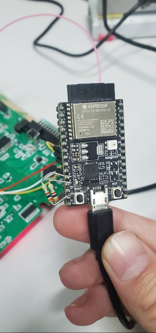
- the project will look something like this - stupidly wired connections between the Arduino board and AD7730. On a good note, I need to take readings from a strain gauge sensor for scales through AD7730, but this is not about that now.
- Yesterday my arduino nano burned out, now I use ESP32-C3-DevKidC-02v1.1
- the wiring diagram for this green ad7730 microcontroller board, this is the maximum that I can provide. The question is to be able to read the ad7730 register in the arduino development environment, I already had the code that Tom sent, it's just kind of useless, it sends the same numbers all the time, regardless of what is connected there or not.

Can I suggest you get a bread board for your project?

Tom.. :smiley: :+1: :coffee: :australia:

thanks, i have it. In this case, it is not needed, all connections are made directly, you can see in the photo)

If I understand correctly, your ADC is on the big PCB, and there are another components too.
Are you sure that these components do not affect on the signals between arduino and ADC chip?

I'm sure the components do not affect in any way, the microprocessor interfered, but we turned it off, it does not interfere

So you must ask yourself why. They don't just burn out of there own accord. You must have done something wrong.

So now you need level shifters on the SPI lines or you will burn this out as well.