Hey guys,
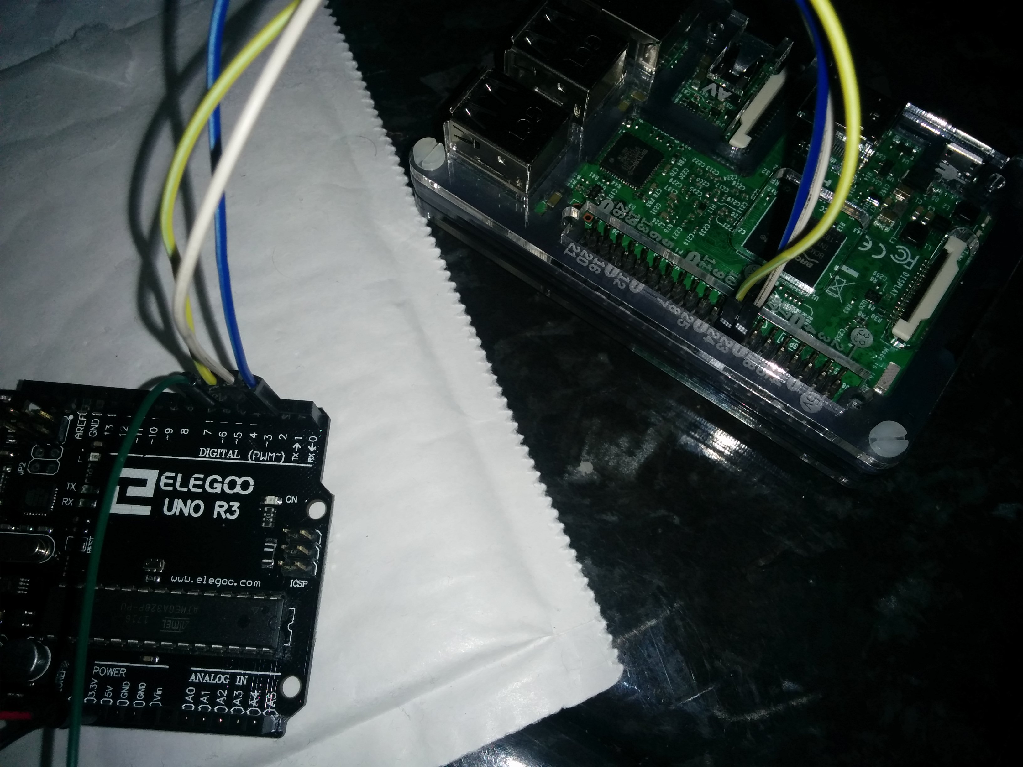
I'm building an Arcade cabinet, and I wanted to control the WS2811 5mm LEDS that will go into my arcade buttons, so that they changed based on the emulator being loaded.
This is done by having the RPI3 send HIGH/LOW signals to the Arduino which are stored as int's then combined into a string and read as an INT to give the illusion of a 3bit message.
I managed to get it all to work flawlessly, however recently out of nowhere, whenever my RPI3 sends out 000 (ALL LOW) the Arduino is reading high sometimes, causing a flicker as it bounces between its case statements.
(By "Flicker" i mean its reading DEFAULT 000 (White) and then SNES 001 (Purple) or N64 100 (Yellow)
Below you can see the readout from the Serial Monitor
DEFAULT MODE
0
DEFAULT MODE
0
SEGA MODE
11
DEFAULT MODE
0
DEFAULT MODE
0
DEFAULT MODE
0
PS1 MODE
10
DEFAULT MODE
0
SEGA MODE
11
DEFAULT MODE
0
DEFAULT MODE
0
DEFAULT MODE
0
DEFAULT MODE
0
DEFAULT MODE
0
DEFAULT MODE
0
DEFAULT MODE
0
SNES MODE
1
DEFAULT MODE
0
DEFAULT MODE
0
PS1 MODE
10
DEFAULT MODE
0
SEGA MODE
11
DEFAULT MODE
0
DEFAULT MODE
0
DEFAULT MODE
0
DEFAULT MODE
0
SEGA MODE
11
DEFAULT MODE
0
DEFAULT MODE
0
SEGA MODE
11
DEFAULT MODE
0
DEFAULT MODE
0
DEFAULT MODE
0
N64 MODE
100
N64 MODE
100
DEFAULT MODE
0
DEFAULT MODE
0
PS1 MODE
10
DEFAULT MODE
0
SNES MODE
1
DEFAULT MODE
0
DEFAULT MODE
0
SNES MODE
1
DEFAULT MODE
0
DEFAULT MODE
0
PS1 MODE
10
SNES MODE
1
SNES MODE
1
SNES MODE
1
SNES MODE
1
SNES MODE
1
SNES MODE
1
SNES MODE
1
SNES MODE
1
SNES MODE
1
SNES MODE
1
SNES MODE
1
SNES MODE
1
SNES MODE
1
SNES MODE
1
SNES MODE
1
SNES MODE
1
SNES MODE
1
SNES MODE
1
SNES MODE
1
SNES MODE
1
SNES MODE
1
SNES MODE
1
SNES MODE
1
SNES MODE
1
SNES MODE
1
SNES MODE
1
SNES MODE
1
SNES MODE
1
SNES MODE
1
SNES MODE
1
SNES MODE
1
SNES MODE
1
SNES MODE
1
SNES MODE
1
SNES MODE
1
SNES MODE
1
SNES MODE
1
SNES MODE
1
SNES MODE
1
SNES MODE
1
SNES MODE
1
SNES MODE
1
SNES MODE
1
SNES MODE
1
SNES MODE
1
SNES MODE
1
SNES MODE
1
SNES MODE
1
SNES MODE
1
SNES MODE
1
SNES MODE
1
SNES MODE
1
SNES MODE
1
SNES MODE
1
SNES MODE
1
SNES MODE
1
SNES MODE
1
SNES MODE
1
SNES MODE
1
SNES MODE
1
SNES MODE
1
SNES MODE
1
SNES MODE
1
SNES MODE
1
SNES MODE
1
SNES MODE
1
SNES MODE
1
SNES MODE
1
SNES MODE
1
SNES MODE
1
SNES MODE
1
SNES MODE
1
SNES MODE
1
SNES MODE
1
SNES MODE
1
SNES MODE
1
SNES MODE
1
SNES MODE
1
SNES MODE
1
PS1 MODE
10
PS1 MODE
10
PS1 MODE
10
PS1 MODE
10
PS1 MODE
10
PS1 MODE
10
PS1 MODE
10
PS1 MODE
10
PS1 MODE
10
PS1 MODE
10
PS1 MODE
10
PS1 MODE
10
PS1 MODE
10
PS1 MODE
10
PS1 MODE
10
PS1 MODE
10
PS1 MODE
10
PS1 MODE
10
PS1 MODE
10
PS1 MODE
10
PS1 MODE
10
PS1 MODE
10
PS1 MODE
10
PS1 MODE
10
PS1 MODE
10
PS1 MODE
10
PS1 MODE
10
PS1 MODE
10
PS1 MODE
10
PS1 MODE
10
PS1 MODE
10
PS1 MODE
10
PS1 MODE
10
PS1 MODE
10
PS1 MODE
10
PS1 MODE
10
PS1 MODE
10
PS1 MODE
10
PS1 MODE
10
PS1 MODE
10
PS1 MODE
10
PS1 MODE
10
PS1 MODE
10
Being an integer it won't read the ZERO's that proceed the number 1 as they are considered redundant when displaying/interpreting the number 1 (0000001 == 1 or 01 == 1)
/*          STATES

  DEFAULT =   000
  SNES    =   001
  PS1     =   010
  SEGA    =   011
  N64     =   100


*/

// Variables
#include <Adafruit_NeoPixel.h>
#define PIN            6
#define NUMPIXELS      2


// Cast Neopixel to pixels and set the LED's up
Adafruit_NeoPixel pixels = Adafruit_NeoPixel(NUMPIXELS, PIN, NEO_RGB + NEO_KHZ800);


// Name these DIGITAL Pins for easy reference
const int RPI1 = 2;
const int RPI2 = 3;
const int RPI3 = 4;

// Create a BIT in the form of a STRING
String result = String(digitalRead(RPI1)) + String(digitalRead(RPI2)) + String(digitalRead(RPI3));


void setup()
{
  // Set the DIGITAL pins as INPUTS - Accept data from the RPI3
  pinMode(RPI1, INPUT);
  pinMode(RPI2, INPUT);
  pinMode(RPI3, INPUT);

  // Required to read the data in on the SERIAL MONITOR
  Serial.begin(9600);

  // This initializes the NeoPixel library.
  pixels.begin();

}

void loop()
{
  result = String(digitalRead(RPI1)) + String(digitalRead(RPI2)) + String(digitalRead(RPI3));
  result.toInt();


  /* Update the BIT STRING at the start of every loop
     Use as a Switch Case
  */

  pixels.show();

  switch (result.toInt())
  {
    // DEFAULT MODE
    case 000:
      Serial.println("DEFAULT MODE");
      Serial.println(result.toInt());

      pixels.setPixelColor(0, pixels.Color(150, 150, 150));
      pixels.setPixelColor(1, pixels.Color(150, 150, 150));

      break;

    // SNES MODE
    case 001:
      Serial.println("SNES MODE");
      Serial.println(result.toInt());

      pixels.setPixelColor(0, pixels.Color(150, 0, 150));
      pixels.setPixelColor(1, pixels.Color(150, 0, 150)); // PURPLE


      break;

    // PS1 MODE
    case 10:
      Serial.println("PS1 MODE");
      Serial.println(result.toInt());

      pixels.setPixelColor(0, pixels.Color(150, 0, 0));
      pixels.setPixelColor(1, pixels.Color(0, 0, 150));

      break;

    // SEGA MODE
    case 11:
      Serial.println("SEGA MODE");
      Serial.println(result.toInt());

      pixels.setPixelColor(0, pixels.Color(150, 0, 0));
      pixels.setPixelColor(1, pixels.Color(150, 0, 0));

      break;


    // N64 MODE
    case 100:
      Serial.println("N64 MODE");
      Serial.println(result.toInt());

      pixels.setPixelColor(0, pixels.Color(150, 150, 0));
      pixels.setPixelColor(1, pixels.Color(150, 150, 0));

      break;

  }

}

void rainbow()
{
  uint16_t i, j;

  for (j = 0; j < 256; j++)
  {
    for (i = 0; i < pixels.numPixels(); i++) {
      pixels.setPixelColor(i, Wheel((i + j) & 255));
    }
    pixels.show();
    delay(20);
  }
}

// Input a value 0 to 255 to get a color value.
// The colours are a transition r - g - b - back to r.

uint32_t Wheel(byte WheelPos) {
  WheelPos = 255 - WheelPos;
  if (WheelPos < 85) {
    return pixels.Color(255 - WheelPos * 3, 0, WheelPos * 3);
  }
  if (WheelPos < 170) {
    WheelPos -= 85;
    return pixels.Color(0, WheelPos * 3, 255 - WheelPos * 3);
  }
  WheelPos -= 170;
  return pixels.Color(WheelPos * 3, 255 - WheelPos * 3, 0);
}
Above you can see the switch statement the Arduino is running, what I find particularly odd is the fact the Arduino only flickers (reads random HIGH signals) when it receives 000. All the other states hold solid and strong and show no signs of misreading the RPI3 GPIO output signal.
Below is the code running on the RPI3.
import RPi.GPIO as IO
import time

IO.setmode(IO.BCM)
pin1 = 22
pin2 = 23
pin3 = 24

IO.setup(pin1, IO.OUT)
IO.setup(pin2, IO.OUT)
IO.setup(pin3, IO.OUT)

while True:
    IO.output(pin1, IO.LOW)
    IO.output(pin2, IO.LOW)
    IO.output(pin3, IO.LOW)
    print("DEFAULT")
    time.sleep(2)
    IO.output(pin1, IO.LOW)
    IO.output(pin2, IO.LOW)
    IO.output(pin3, IO.HIGH)
    print("SNES")
    time.sleep(2)
    IO.output(pin1, IO.LOW)
    IO.output(pin2, IO.HIGH)
    IO.output(pin3, IO.LOW)
    print("PS1")
    time.sleep(2)
    IO.output(pin1, IO.LOW)
    IO.output(pin2, IO.HIGH)
    IO.output(pin3, IO.HIGH)
    print("SEGA")
    time.sleep(2)
    IO.output(pin1, IO.HIGH)
    IO.output(pin2, IO.LOW)
    IO.output(pin3, IO.LOW)
    print("N64")
    time.sleep(2)
I can't understand why it would only read incorrectly when it receives 000, it would make more sense if it flickered all the time meaning the RPI3 isn't providing a proper LOW signal or the arduino is struggling to read the LOW signal. Either of which would at least mean the error lies in some damaged GPIO ports.
What are your thoughts on this?