Arduino Freezez when pumps are turning

Hi!
I am using 2 submergible 3-6V water pumps.
When the pumps are actioned, after a short while the Arduino freezes.
I tried to put 0.1uF ceramic capacitors between the motor leads and between each power lead and GND, but I can't say I saw much improvement. I also tried putting electrolytic capacitors almost everywhere in hope of filtering some of the noise induced by the pumps in the circuit, but no success.

I tried powering separately the logic circuit with a 9V battery and use the LI-ION pack only for the motors, but no difference.


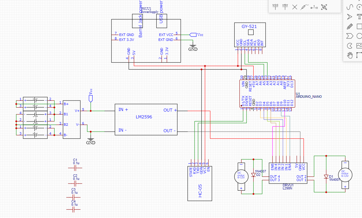
Here is the circuit. I also uploaded the code I'm using for testing the basic functionality.

#include <Wire.h>
#include <Arduino.h>

#define MPU6050_ADDR 0x68

// Definirea pinilor pentru L298N
#define MotorA_Enable 9   // Pinul PWM pentru controlul vitezei Motorului A
#define MotorA_Directie1 3 // Pinii de directie pentru Motorul A
#define MotorA_Directie2 4

#define MotorB_Enable 10  // Pinul PWM pentru controlul vitezei Motorului B
#define MotorB_Directie1 5 // Pinii de directie pentru Motorul B
#define MotorB_Directie2 6

void setup() {
  Wire.begin();
  Wire.beginTransmission(MPU6050_ADDR);
  Wire.write(0x6B);  
  Wire.write(0x00);  
  Wire.endTransmission(true);

  Serial.begin(115200);

  // Initializarea pinilor de control pentru L298N
  pinMode(MotorA_Enable, OUTPUT);
  pinMode(MotorA_Directie1, OUTPUT);
  pinMode(MotorA_Directie2, OUTPUT);

  pinMode(MotorB_Enable, OUTPUT);
  pinMode(MotorB_Directie1, OUTPUT);
  pinMode(MotorB_Directie2, OUTPUT);
}

void loop() {
  double angle = readGyroAngle();

  // Controlul Motorului A
  if (angle > 1.0) {
    digitalWrite(MotorA_Directie1, HIGH);
    digitalWrite(MotorA_Directie2, LOW);
    analogWrite(MotorA_Enable, 180); // Viteza medie
  } else {
    analogWrite(MotorA_Enable, 0); // Oprire Motorul A
  }

  // Controlul Motorului B
  if (angle < -1.0) {
    digitalWrite(MotorB_Directie1, HIGH);
    digitalWrite(MotorB_Directie2, LOW);
    analogWrite(MotorB_Enable, 180); // Viteza medie
  } else {
    analogWrite(MotorB_Enable, 0); // Oprire Motorul B
  }

  Serial.print("Angle: ");
  Serial.print(angle);
  Serial.println();

  delay(20);  
}

double readGyroAngle() {
  Wire.beginTransmission(MPU6050_ADDR);
  Wire.write(0x3B);
  Wire.endTransmission(false);
  Wire.requestFrom(MPU6050_ADDR, 6, true);
  
  int16_t AccelX, AccelY, AccelZ;
  AccelX = Wire.read() << 8 | Wire.read();
  AccelY = Wire.read() << 8 | Wire.read();
  AccelZ = Wire.read() << 8 | Wire.read();

  double angle = atan2(AccelY, AccelZ) * 180 / PI;
  return angle;
}

try with separated powering of motor driver. D1/D2 diodes are not needed.

There is no common GND wiring.

1 Like

Tried powering the logic part with a 9V battery and the motor with the battery pack. No change.

post#3
connect GND of Nano to GND of driver

Just put another wire between the output GNDs of the buck converters. No difference.

show on the picture. i suppose you made no additional connection (especially not asked one), another words no difference to previous schema, that is why you get no difference in behavior of pumps.

try this simple sketch

// Definirea pinilor pentru L298N
#define MotorA_Enable 9   // Pinul PWM pentru controlul vitezei Motorului A
#define MotorA_Directie1 3 // Pinii de directie pentru Motorul A
#define MotorA_Directie2 4

#define MotorB_Enable 10  // Pinul PWM pentru controlul vitezei Motorului B
#define MotorB_Directie1 5 // Pinii de directie pentru Motorul B
#define MotorB_Directie2 6

void setup() {
  // Initializarea pinilor de control pentru L298N
  pinMode(MotorA_Enable, OUTPUT);
  pinMode(MotorA_Directie1, OUTPUT);
  pinMode(MotorA_Directie2, OUTPUT);

  pinMode(MotorB_Enable, OUTPUT);
  pinMode(MotorB_Directie1, OUTPUT);
  pinMode(MotorB_Directie2, OUTPUT);
  digitalWrite(MotorA_Directie1, HIGH);
  digitalWrite(MotorA_Directie2, LOW);
  digitalWrite(MotorB_Directie1, HIGH);
  digitalWrite(MotorB_Directie2, LOW);
}

void loop() {
  analogWrite(MotorA_Enable, 180); // Viteza medie
  analogWrite(MotorB_Enable, 180); // Viteza medie
  delay(2000);
  analogWrite(MotorA_Enable, 255);
  analogWrite(MotorB_Enable, 255);
  delay(2000);
}

replace diodes with capacitors

+1
They are in fact a danger to the driver if you reverse the H-bridge. Remove..

Pumps usually don't need to be reversed. So it's much better if you connect the pump between OUT1 and ground, and the other pump between OUT3 and ground. That halves the losses in the L298. It could also be better if you power the L298 directly with 12volt (no LM2596), and use PWM to regulate pump power.
The HC-05 is connected to pin 0,1, and that interferes with the serial monitor.
It should be connected with SoftwareSerial to two different pins, and the RX pin of the HC-05 should have a 2-resistor level converter, because it's a 3.3volt-logic device.
Leo..

Hi, @andreiliviu4

Your best alternative is to use a single MOSFET switch on each pump if you only drive the pumps in one direction.

Forget the motor driver.

Tom... :grinning: :+1: :coffee: :australia: