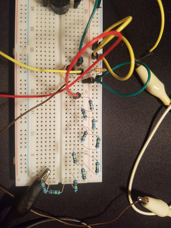
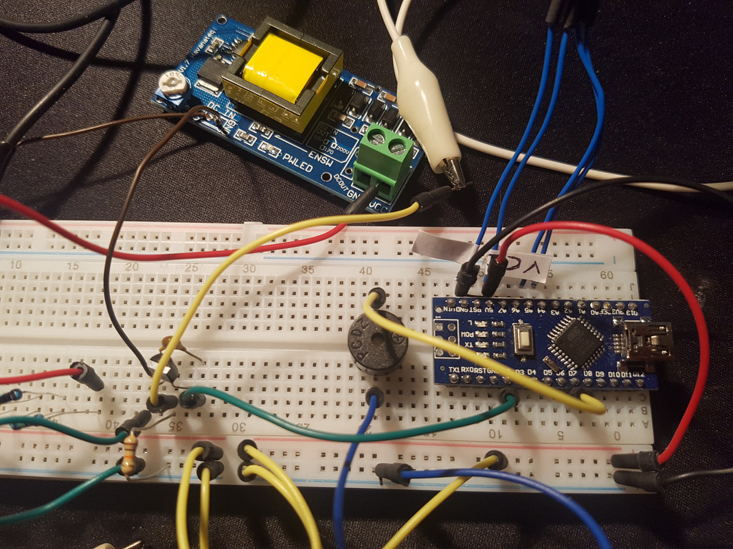
I bought everything i need, but in the moment i connected all the components on my breadboard, the arduino counter wont increase.
I don't have an oscilloscope in my home, it's been years, now, that I no longer deal with electronics.
If i measure the sbm-20 with my multimeter the counter start increase.
So i think the problem is not the circuit itself but the tube, or the resistance that i have on the anod of the tube (10Mohm), that drop the voltage to 250V instead of 400V.
i tried to connect the D2 to GND and the counter increase.
I tried to change the 10Mohm resistance to 4.7Mohm, with 27Kohm resistance on the transistor, but the counter won't increase.
I tried to change the transistor, but the counter won't increase.
I added to the code the Serial.println(bt); to see if the counter increase when i use the multimeter, and it does.
I don't know what to do, and i spent money to do this project, i won't leave it. Can you guys help me?
I'm trying to do this project. http://www.instructables.com/id/DIY-Arduino-Geiger-Counter/
I bought everything i need, but in the moment i connected all the components on my breadboard, the arduino counter wont increase.
I don't have an oscilloscope in my home, it's been years, now, that I no longer deal with electronics.
If i measure the sbm-20 with my multimeter the counter start increase.
So i think the problem is not the circuit itself but the tube, or the resistance that i have on the anod of the tube (10Mohm), that drop the voltage to 250V instead of 400V.
i tried to connect the D2 to GND and the counter increase.
I tried to change the 10Mohm resistance to 4.7Mohm, with 27Kohm resistance on the transistor, but the counter won't increase.
I tried to change the transistor, but the counter won't increase.
I added to the code the Serial.println(bt); to see if the counter increase when i use the multimeter, and it does.
I don't know what to do, and i spent money to do this project, i won't leave it. Can you guys help me?
What transistor are you using and have you checked the pinouts and all the breadboard connections?
What are you using to trigger the Geiger tube?
Tom......
the transistor is the 2N3904.
when I take the tube out from the circuit, if i connect the terminals, the counter increase.
i checked the pinouts lot of times, they are correct.
the tube let the current flow when ionizing radiation hit the tube.
this event trigger the transistor, that makes the d2 pin going to ground, and increase the counter.
Dragonero:
... or the resistance that i have on the anod of the tube (10Mohm), that drop the voltage to 250V instead of 400V.
I suppose you know that if you measure a voltage through a 10Megohm resistor with a DMM with a 10Megohm internal resistance, that you only see half the voltage on your DMM (1:1 voltage divider).
Leo..
I'm using a dmm with 10mohm impedence, so the measurement that i see isnt true?
I'm expecting some kind of voltage drop on the 10mohm resistor...
The tube works with 380v-420v and i see only 250V out from resistor series..
I picked up a small, inexpensive DMM that works fine, but it has only 1 Megohm input resistance on the DC voltage ranges. So, it appears as a significant load to high impedance, high voltage sources.
The device appears similar to this one. (EDIT: I paid more than USD 0.99 though).
So be careful with voltage dividers and make sure that you understand the circuit loading issue. The test with the 9V battery suggested above is a good one.
I think i've "solved" the problem, is not the best way but it works.
I connected the tube to this schematic
Then i've connected the pin3 of the ne555 to the D2 of arduino.
Setting the D2 to low, the counter start increasing, and if i disconnect the tube it will stop.
Instructbles are by and large crap written by people who think they know a lot more than they do. Sadly this is the case here. That transistor is going to die quite soon from excess voltage spikes. Sure the current is very low but you are punching holes through the base all the time and the transistor is slowly degrading.
allanhurst:
How much avalanche current does a GM tube produce? A simple clamp may make it workable.
Basically when the tube detects a gamma ray it is shorted out, so it is the 10M that is limiting the current. So with 10M and 400V you will get a current of 40uA.
When I published my Geiger counter project in 1986 I used this circuit:-