So I built myself a circuit that controls a fan using a mosfet and arduino.
When I don't have the arduino plugged in the circuit and I give the gate negative or positive it works, the fan turns off and on.
But when I plug the ground of the arduino in the source and plug the gate into pin 10 of the PWM pins on the arduino and I try to control it using code, it doesn't work. Even after that when I remove the arduino from the circuit and I give the gate positive or negative it doesn't work anymore! I have to remove the mosfet and plug it back in.
lastchancename: @bluejets...
Where did you see his code ?
If you read my post you can see I have link in there referring to my code but I might as well post it here:
//Variables
int fanPin = 10; //Fan is plugged into PWM 10

void setup() {
  // put your setup code here, to run once:
  pinMode(fanPin, OUTPUT);
  digitalWrite(fanPin, HIGH); //HIGH
}

void loop() {
  // put your main code here, to run repeatedly:
}
Nothing in your code is turning it off by the way.
I'll try that soon, thanks a lot.
I know my code isn't turning it off, whenever I wanted to turn the fan off I just put LOW instead of HIGH and upload it and see if it works.
I don't have a 1k resistor. Am I able to use four 220 ohm resistors and one 120 ohm resistor in series? (Yes I know it is bunk but I need to know if it can work.)
And could you maybe edit the image of the circuit I posted since it's kind of confusing to me.
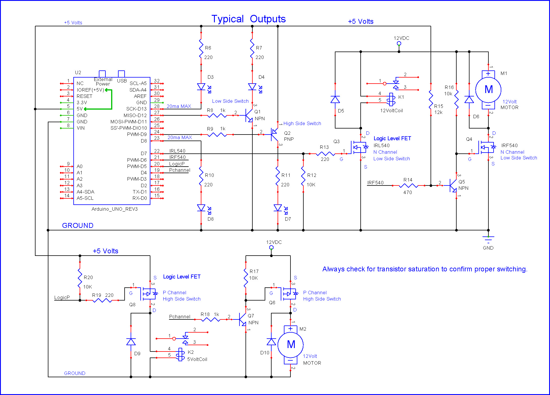
The Q3 circuit is similar to yours, the relay in the drain would be exchanged for your fan.
Note the 10K and 220 resistor placement in the gate area.
Of course you need a logic level MOSFET when the Arduino controls it directly.
As mentioned, you are not controlling the fan in your loop() function.
Maybe put more thought into what you want to do.
void loop()
{
// put your main code here, to run repeatedly:
}
I'm sorry but that diagram is a little to hard for me to understand, I just started arduino and that's why I am asking if you could edit the image I posted in my initial post to show me where the resistors go.
I am using a logic level mosfet I also linked that in the initial post.
I'm not going to worry about code for now since I first need to make the system work, thats why I online input HIGH in the setup.