Hi,
First of all Im completely new to electronics and this forum, so Im on the lower level of understanding.
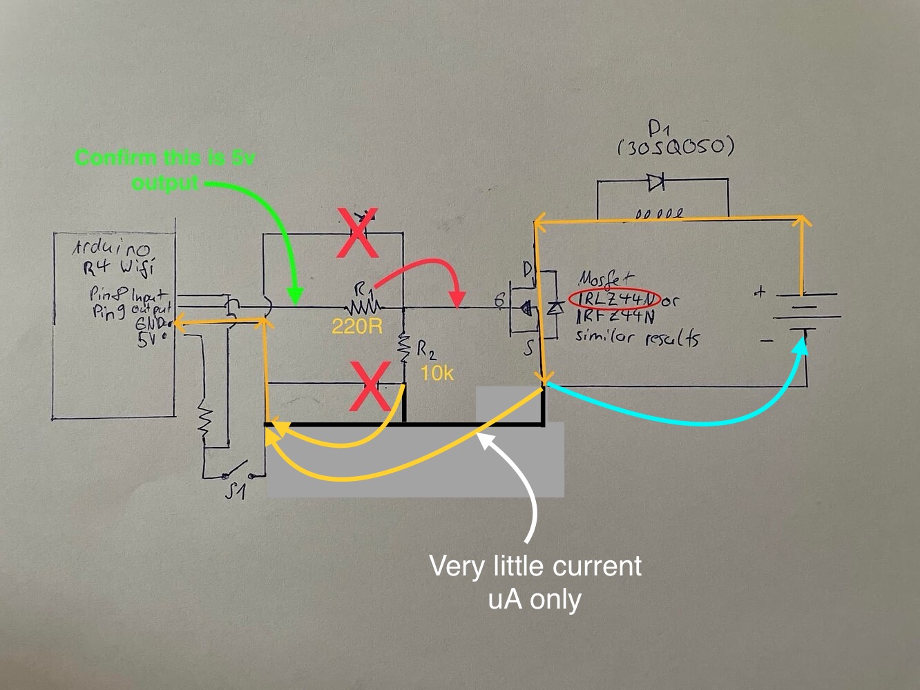
I have some very strange scenario where I use an Arduino R4 Wifi to control an MOSFET directly over pin 9, defined as OUTPUT. It is a programmed sequence that starts with a button signal on pin 8, defined as INPUT.
In the code pin 9 is set to LOW on startup and then to HIGH for 1500ms, followed by LOW on an input signal from pin 8.
I purchased N-Channel MOSFETS (IRLZ44N) from "ALLECIN" on Amazon and they started working as expected. However now they dont. I read a lot and changed the wires, added resistors and so on until I concluded, that i destroyed them due to not adding a flyback diode to the inductive 12V load. Now added. I then ordered more MOSFETS. Accidentally IRFZ44N instead of the logic gate equivalent.
All of the MOSFETS are open and allow current, wihtout any gate voltage applied. To make sure the pins are on LOW, i added leds to the curcuit and they indeed only turn on as supposed within the sequence. However the inductive load is charged as soon as i physically connect the power source.
I tried 11000 and 1001000 ohm resistors between gate and ground. The odd numbers are due to the fact 2 resistors are in series. The 1000 ohm resistor is between the pin and gate as i dont need high frequency PWM signals to control the MOSFET.
I have made sure the diodes are connected the right way.
Also i had to add a diode between gate and ground as i noticed that the ground pin was charging the gate. I did this by disconnecting all other power sources and pins until the ground pin of the Arduino was the last thing connected with the gate and the breadboard.
I probably forgot a lot of details and i tried quite some configurations. I also read about fake MOSFETS being sold. Im clueless right now why the MOSFETS are not working as expected and i wonder if the Arduino output pins are perhaps leaking a little bit of power, not enough for the leds but enough for the gate. Weirdly it also turns on the IRFZ gates, which are supposed to need a much higher voltage. Also its worth to note that the inductive load started to "flatter".. like i would have used a PWM signal instead of a continuos one. Very strange. I have also tried different pins: 5, 6, 7.
I do be sorry for the messy setup. It was orignally more complicated so I reduced it to the problem.
Greetings ![]()


I was only allowed to add 3 pictures. Ill to choose the most important.