Yep, adding bounce to the rising and falling edges of a pwm signal messes things up ...
Now to add software debounce ...
Yep, adding bounce to the rising and falling edges of a pwm signal messes things up ...
Now to add software debounce ...
OK, now its debounced in the ISR. Limited to 2000μs (500Hz or 30,000rpm). With input signal on pin 2 really messed up with random bounce pattern, getting accurate and stable results ...
#include <LiquidCrystal_I2C.h>

const byte   wings = 4; // no of wings of rotating object, for disc object use 1 with white tape on one side
volatile unsigned long us, prevPulseUs, pulseUs, prevPulseUsCopy, pulseUsCopy;
unsigned long pulsePeriod, rpm;

void isr() { //interrupt service routine
  us = micros();
  if ((us - pulseUs) > 2000) { //limited to 500Hz max
    prevPulseUs = pulseUs;
    pulseUs = us;
  }
}

bool timeOut(unsigned long ms) { //ms timer
  volatile unsigned long prevMs, now;
  now = millis();
  if ((now - prevMs) >= ms) {
    prevMs = now;
    return true;
  }
  return false;
}

LiquidCrystal_I2C lcd (0x27, 16, 2);

void setup() {
  pinMode(3, OUTPUT);  // pwm test: disconnect sensor, then add jumper from pin 2 to 3
  analogWrite(3, 127); // pwm @ 490 Hz = 29400 rpm / wings

  lcd.init(); //initialize LCD
  lcd.backlight(); //turn on the backlight on LCD
  attachInterrupt(digitalPinToInterrupt(2), isr, RISING); //attaching the interrupt
}

void loop() {

  if (timeOut(1000)) {
    cli(); //stop interrupts
    prevPulseUsCopy = prevPulseUs;
    pulseUsCopy = pulseUs;
    sei(); //allow interrupts
    pulsePeriod = pulseUsCopy - prevPulseUsCopy;
    if (!pulseUsCopy || !prevPulseUsCopy) pulsePeriod = 10000000; // startup 0 rpm

    rpm = 1000000 / pulsePeriod * 60 / wings; //calculates rpm
    lcd.clear();
    lcd.setCursor(0, 0);
    lcd.print("___TACHOMETER___");
    lcd.setCursor(0, 1);
    lcd.print(rpm);
    lcd.print(" RPM");
    lcd.print(" ");
  }
}
If your sensor signal looks more like this (normally low), then use RISING ...
If your sensor signal looks more like this (normally high), then use FALLING ...
If your sensor signal looks more like a square wave, then use RISING or FALLING ...
This will allow software debouncing to work correctly.
Hi guys. Thank for your replies sorry it’s taken a while to get back to you, your help is appreciated though.
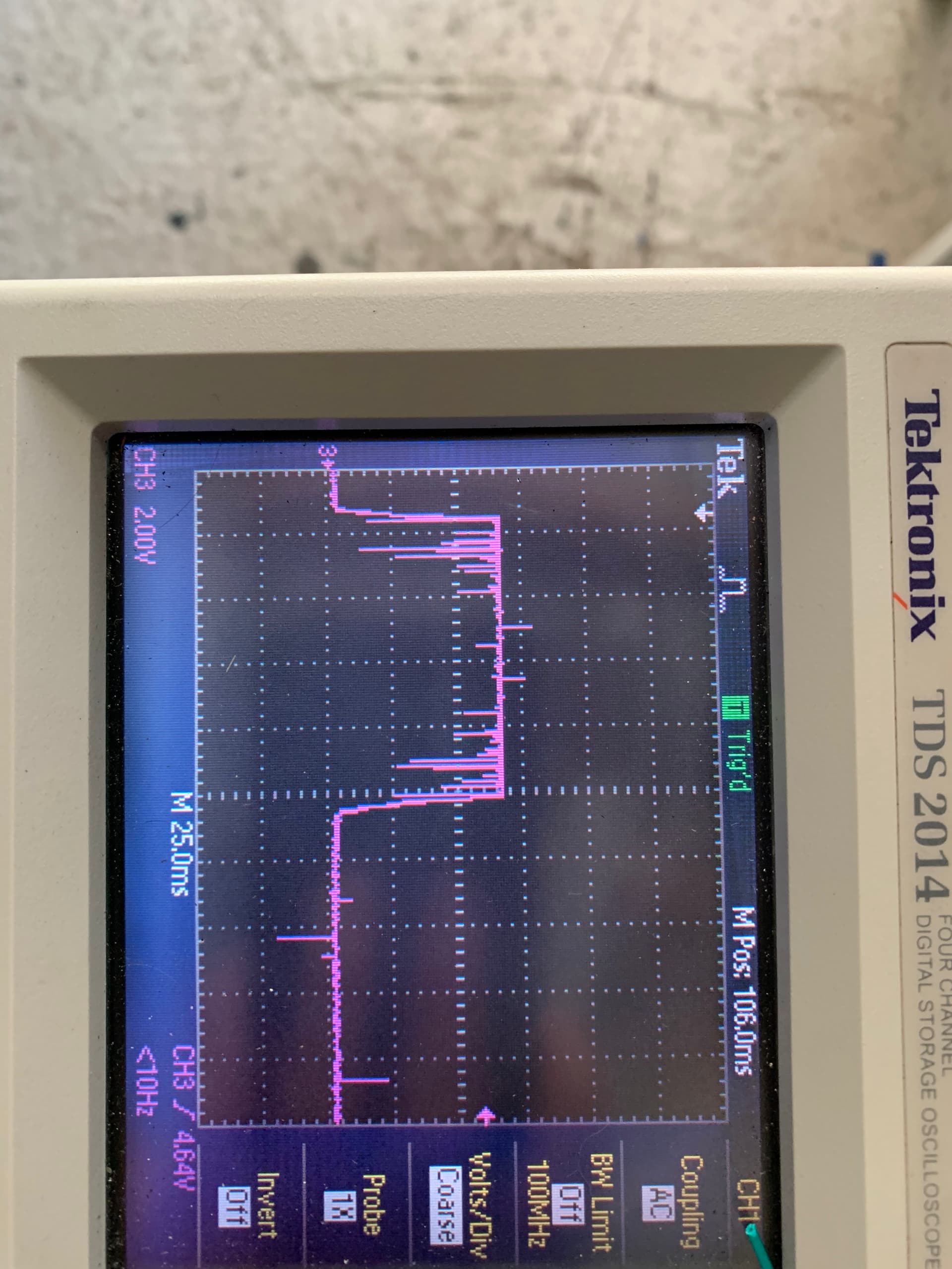
I’ve stumbled on two issues. It would appear using pin 13 to power the IR doesn’t provide enough power for a good o/p and I’m also still getting noise on the o/p pulse when the vfd is running. (See below)
Until I can get the noise sorted I’m a bit stuck with the programming ![]()
You don't even need to use a digital pin for the IR LED. You could just power it directly off the 5V supply and a current limiting resistor.
And is the VFD cable grounded on both ends?
Shielded cable for return to the Arduino?
The noise is mostly near the pulse edges, but is also completely random throughout the pulse duration. Therefore, a common debounce method (with ignore period) won't work.
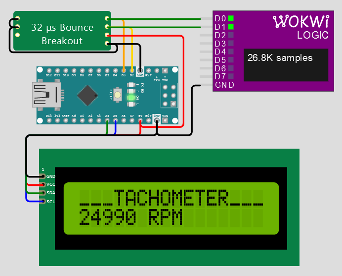
I think a more robust solution would be to add the Toggle library, where it takes 3 stable input readings to either set or reset the output (like this debounce algorithm).
The characteristics of the noise is instantaneous ... the Toggle library will have no problem filtering this whether the signal is high or low. I've set the sample period to 100μs and it works fine in the WOKWi simulation below.
Could you give this a try?
Ok so I've managed to sort the noise issue with a low pass filter on the I/P of pin 2 and using a separate power supply for the 3 units. So I'm happy the noise issue is resolved.
Using the code dlloyd in post 22 the RPM reads consistently (using 1 'wing'), but only in multiples to 60. I'm going to have a play with cncnotes code in post 19 and see if I get any different results this afternoon.
thanks again...making slow progress ![]()
Its possible you may still have some spurious noise. If so, the code from post 25 should ignore this.
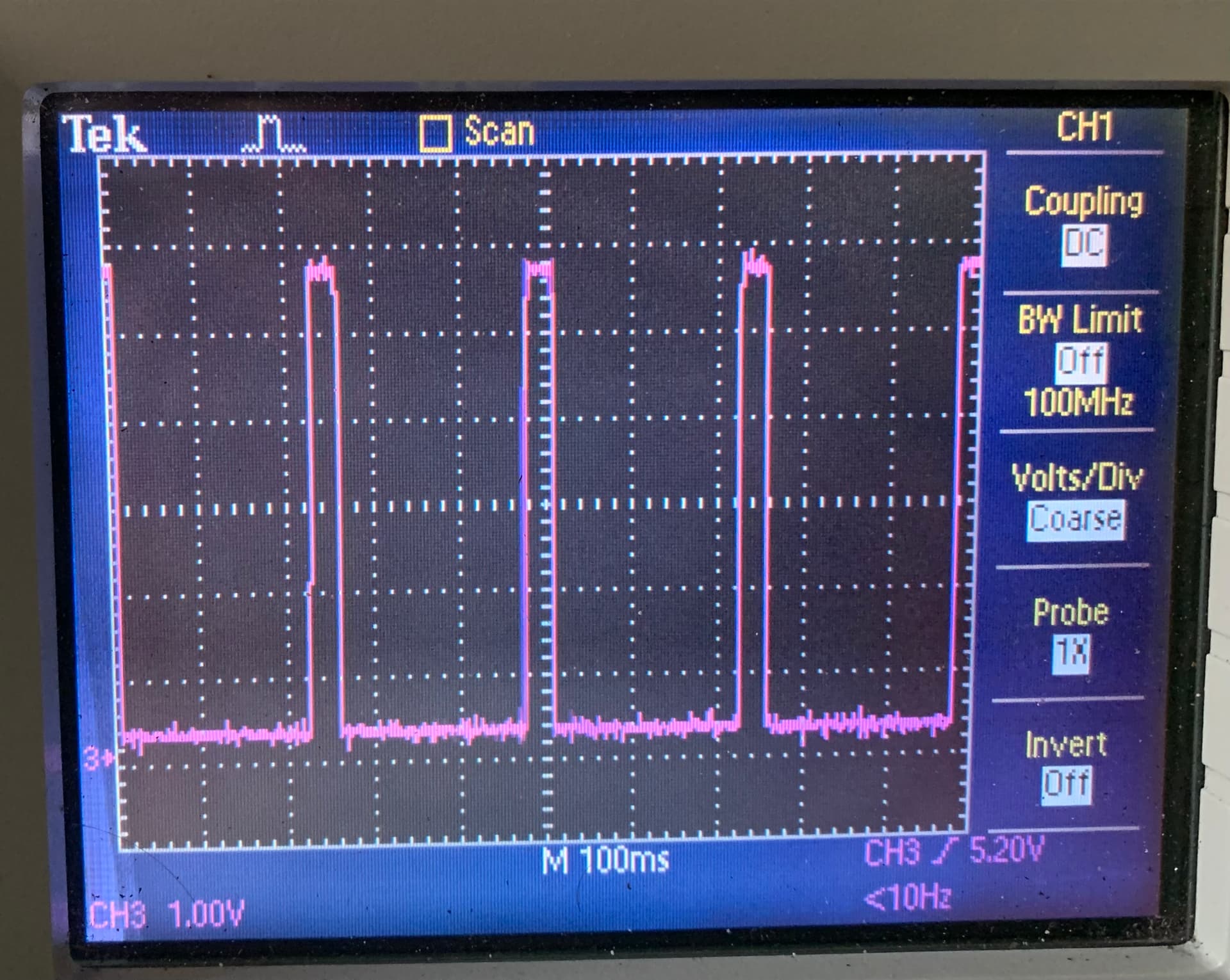
I’ve just tried the code from post 25 and I’m still getting multiples of 60. Pic of I/P 2 attached, I’m pretty confident the noise has been erased. (The 5V power looks clean too)
Would I be better have more ‘wings’ ?
Don't know if the extra wings would make any difference. Your signal looks very clean.
Looking at the scope picture, I estimate a pulse every 180 ms. Is that what you get when you measure it with the scope?
That translates into ~5.5Hz, or 330 rpm. Is that the correct rpm you expect? And if so, what is the Arduino reporting?
rpm = 1000000 / pulsePeriod * 60 / wings; //calculates rpm
You are seeing the effect of integer truncation in this division: 1000000/pulsePeriod.
The multiplication and division math operations proceed from left to right. For example if you have the 180 ms pulse shown, then 1000000/180000 will be truncated to 5 and the reported rpm will be 300. You will only see changes of +/- 60.
Try to put the multiplication by 60 before the division. The UL specifier tells the compiler how to treat the large integer constant. https://www.arduino.cc/reference/en/language/variables/constants/integerconstants/
rpm = 60000000UL / pulsePeriod / wings; //calculates rpm
Hi all, thanks for your help with this it looks like that last amendment from cattledog worked. The Arduino is calculating the same RPM as I'm working out using the scope and visually. I just now need to work out how to fit it to the lathe !
thanks again for everyones help ![]()
![]()
This topic was automatically closed 180 days after the last reply. New replies are no longer allowed.