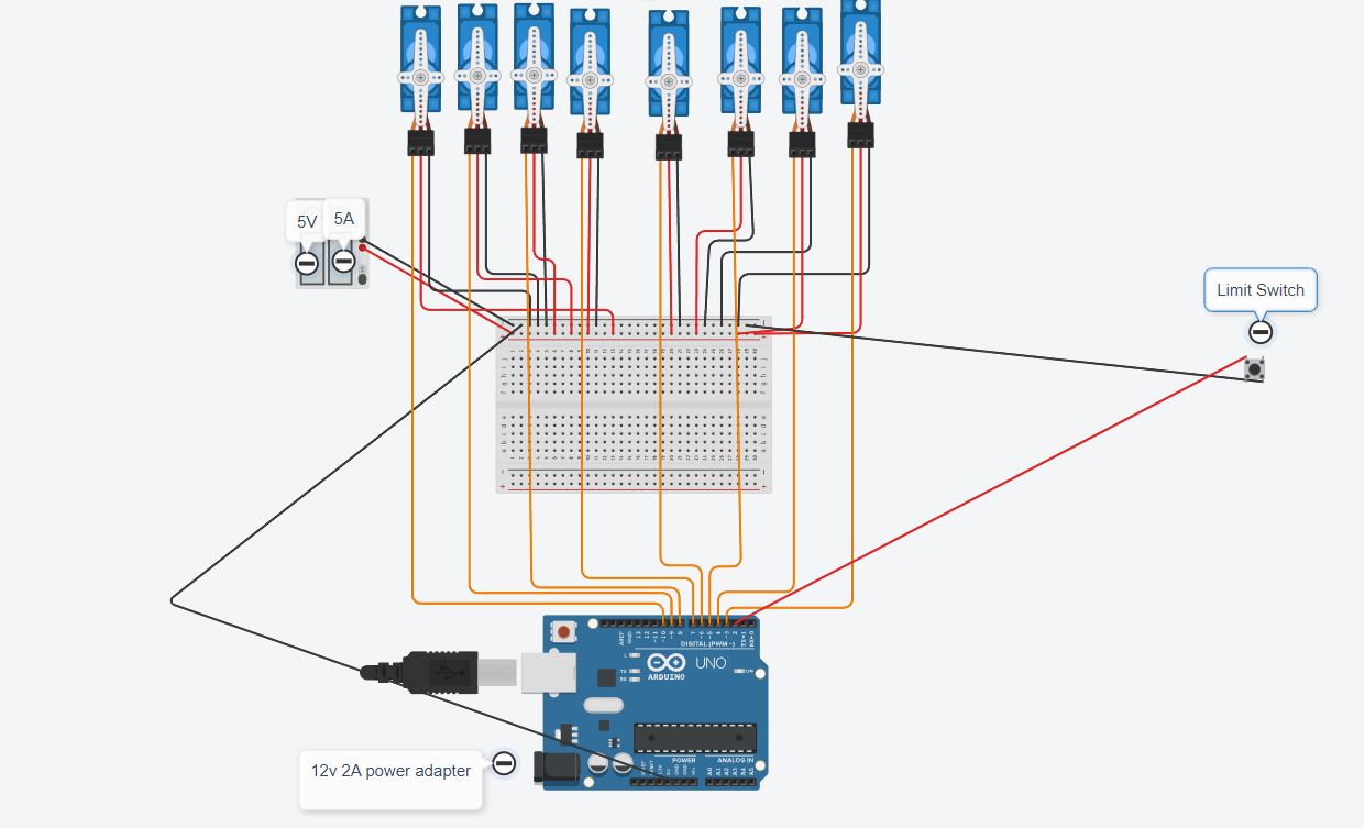
I have an arduino project controling 8 servo motor it functions as follows : i press the button each servo rotates to 90 degree and when all servos are at 10 degrees the all turn back to 0 , i have external 5v 5A power supply for the motors ans external power abapter to arduino i connected 2 220v cooling fans to cool down my components while the fans are connected the sequence starts on its own i disconnect the fans from power the whole thing becomes stable again and only starts when i press the button, what could be the issue here ?
here is my diagram and code:
#include <Servo.h>


#define SWITCH_PIN 2
#define NUM_SERVOS 8
Servo servos[NUM_SERVOS];
bool servosActivated[NUM_SERVOS] = {false};
bool sequenceRunning = false;
// Define the servo pins
const int servoPins[NUM_SERVOS] = {3,4,5,6,7,8,9,10};
void setup() {
  Serial.begin(115200);
  pinMode(SWITCH_PIN, INPUT_PULLUP); // Set up the button with an internal pull-up resistor

  // Attach servos to their respective pins
  for (int i = 0; i < NUM_SERVOS; i++) {
    servos[i].attach(servoPins[i]);
    servos[i].write(0); // Initialize servos to 0 degrees
    delay(500);
    servos[i].detach(); // Detach after setting initial position
  }
  randomSeed(analogRead(0)); // Seed the random number generator
}

void loop() {
  if (digitalRead(SWITCH_PIN) == LOW && !sequenceRunning) {
    Serial.println("Button pressed");
    sequenceRunning = true;
    runSequence();
    resetServos();
    sequenceRunning = false;
  }
}

void runSequence() {
  int remainingServos = NUM_SERVOS;

  while (remainingServos > 0) {
    int servoIndex = randomServo();

    if (servoIndex != -1) {
      delay(1500);
      moveServo(servoIndex);
      servosActivated[servoIndex] = true;
      remainingServos--;
    }
  }

  delay(2000); // Wait 1 seconds before moving all servos back to 0 degrees
  resetServos();
}

int randomServo() {
  int availableServos[NUM_SERVOS];
  int count = 0;

  // Identify which servos haven't moved yet
  for (int i = 0; i < NUM_SERVOS; i++) {
    if (!servosActivated[i]) {
      availableServos[count] = i;
      count++;
    }
  }

  if (count == 0) {
    return -1; // No available servos
  }

  int randomIndex = random(count);
  return availableServos[randomIndex];
}

void moveServo(int servoIndex) {
  servos[servoIndex].attach(servoPins[servoIndex]); // Reattach the servo
  servos[servoIndex].write(90); // Move to 90 degrees
  delay(500); // Wait for the servo to reach the position
  servos[servoIndex].detach(); // Detach the servo after moving
}

void resetServos() {
  // Command all servos to move to 0 degrees at the same time
  for (int i = 0; i < NUM_SERVOS; i++) {
    servos[i].attach(servoPins[i]); // Reattach the servo
    servos[i].write(0); // Move to 0 degrees
  }

  // Wait for all servos to reach the 0 degree position
  delay(500); // Adjust the delay as needed based on the servo speed

  // Detach all servos after they have reached the position
  for (int i = 0; i < NUM_SERVOS; i++) {
    servos[i].detach(); // Detach the servo after moving
    servosActivated[i] = false; // Reset the activated state
  }

  Serial.println("All servos moved to 0 and reset.");
}
Please post your sketch, using code tags when you do. This prevents parts of it being interpreted as HTML coding and makes it easier to copy for examination
In my experience the easiest way to tidy up the code and add the code tags is as follows
Start by tidying up your code by using Tools/Auto Format in the IDE to make it easier to read. Then use Edit/Copy for Forum and paste what was copied in a new reply. Code tags will have been added to the code to make it easy to read in the forum thus making it easier to provide help
You could add a 10K resistor between the input pin and GND to hold the pin normally LOW
Personally I would use INPUT_PULLUP in the pinMode() for the input pin to turn on the built in pullup resistor so no extra hardware is required. If you do this, change the circuit so that pin is taken LOW when the switch is closed and detect LOW in the sketch to indicate that the switch is closed
Please post your sketch using code tags as it is currently unreadable
Yes, if the circuit is wired to take the input LOW when the switch is closed which it seems to be. Unless, of course, the switch is normally closed which cannot be determined from your diagram. This one reason why users are asked to post a schematic rather than a graphical representation of the circuit
the switch is wired normaly closed yes , but if i reverse it and there is an electrical noise wouldn't that create same problem , i mean the switch won't be able to go low when there is noise around it?
You do not need a capacitor connected to the switch. When the switch is wired correctly and INPUT_PULLUP is used in the pinMode() for the input pin the pin will be in a fixed state whether it is open or closed
In your sketch you have the following
if (digitalRead(SWITCH_PIN) == LOW && !sequenceRunning)
    {
        Serial.println("Button pressed");
The state of the switch pin will only be LOW when the switch is closed, but that is its normal state. If you want to detect when the switch is operated, ie opened, then you need to test for HIGH
Have you tried measuring the state of the input pin with a DMM to ensure that it is behaving as expected ?
You don not appear to have a GND connection between the Arduino and the breadboard or power supply. If that is the case then the Arduino is trying to compare the voltage between 2 different systems with no common point of reference