but it looks like it's going to the positive bus on the breadboard
yes you're right i missplaced it, i will correct it in the post
i corrected it in the photo, i missplaced it in the diagram
DO NOT CHANGE YOUR PREVIOUS POST
It makes a nonsense of replies to the post
Post the actual circuit in a new reply
why don't you try wiring a switch directly between ground and pin on arduino anf verify the coding
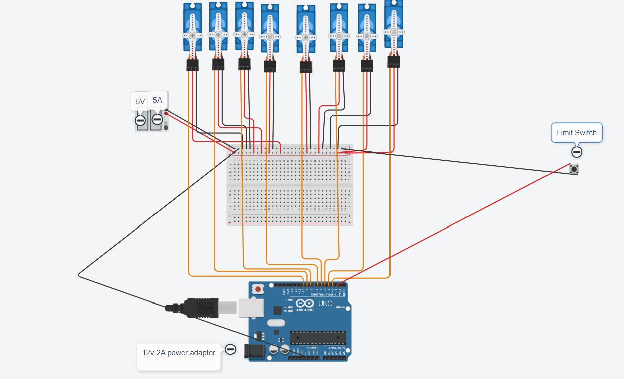
i will actually test that, idk if it will give diffrent result but i should test it
Exactly what type of switch are you using ?
Is it a pushbutton TACT switch as depicted in your diagram and, if so, please post a link to where you got it from. NC switches of that type are unusual
Please also confirm that the connections to it go to 2 diagonally opposite pins

Thank you. That clarifies what type of switch you are using. Do you see why a schematic rather than rather than a inaccurate graphical representation of the circuit
Previously you have said
but now you say
What keeps the switch closed ?
yes my mistake i meant normally open, it's closed only when i press it... i actually don't know what should keep it in NO state till i press it . i'm a newbie excuse me.
If the switch is Normally Open (NO) and the pinMode() of the pin is INPUT_PULLUP then the pin will normally be HIGH
If the switch is wired to take the pin LOW when it is closed then you can detect the closure by testing for that LOW state using digitalRead()
It really is that simple
In this diagram (Originator @LarryD)

your switch is wired like S3
Please confirm that the Arduino, the breadboard and power supplies have all got their GNDs connected together