Hello,
Im trying to get my TFT screen to work, but from power on it only gives me a white screen.
My setup is
Arduino Mega 2560 - CTE TFT LCD Shield (for mega) - tft_320QVT_9341 (40pin).
It pins fit perfectly but somehow i cant get this tft to work.
I tried to run the Demo 320x240 from the UTFT libary.
i changed to the suposted display driver:
UTFT myGLCD(ILI9341_16,38,39,40,41);
But nothing but white screen.
I changed the ILI9341_16 to many others. I even tried the listed 0 to 30 from the UTFT.h file.
Any ideas on what else i can try?
Greeting Guido

There are solder-bridges at the bottom of the 16x2 header. Check that they are correct.
ColdTears have a better reputation for "assembly quality" than Sainsmart.
Your photo and the CTE Ebay site do not have a clear view of those solder-bridges.
Your UTFT constructor looks ok.
David.
Thank you for the reply.
Glad to see i put the right components together, im a bit new on this part.
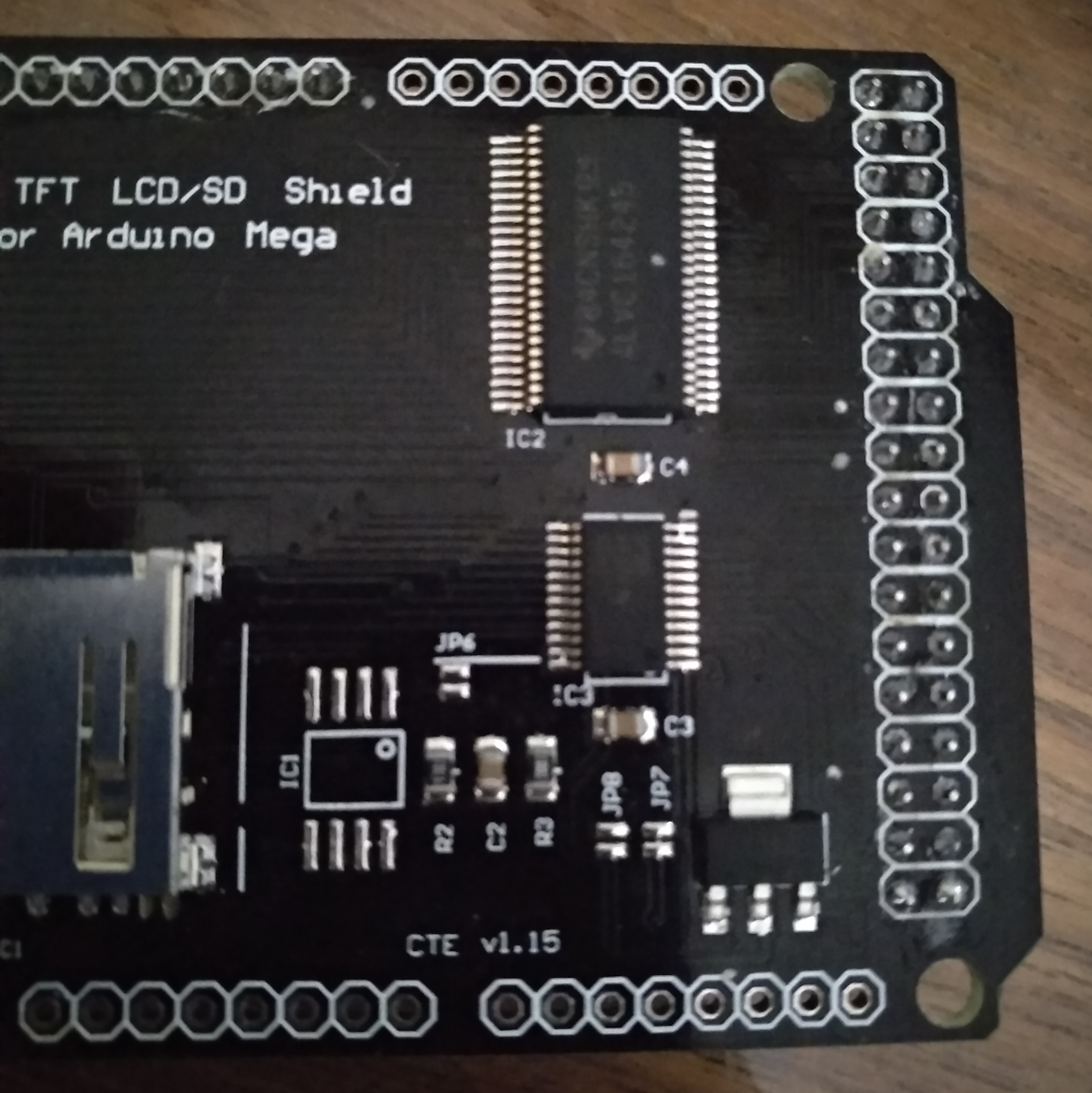
I took a picture of my CTE Shield. You talk about bridges, i think they are visible on the new photo.
On the right of the second row of the 16x2 header i see something what looks like a bad solder?
Also on the bottom of the shield there is a Jumper config diagram. Is there anything a need to change about them / solder? Or is it a sort of software jumper.
Last thing i noticed when i start the combination arduino/shield/tft the TFT is getting very hot.

Nothing should get hot. Some TFTs get warm due to high backlight current. I would expect your QVT to have the correct backlight current.
I can't tell much from your photo. Only you can judge the quality of the soldering. I would expect JP1 to be closed. JP2 to be open.
I have never owned this type of display or Mega Adapter. Many readers do have this hardware and can advise you.
David.
Well, i thought i could use the shield right out of the box, but starts to have doubts.
I only got white backlight, and the side of the pins get warm (not the correct current?).
So on the back of the CTE shield is an infogram jumper config (see photo).
As said, i dint solder anything, but JP 1 to 4 is closed, 5 to 8 are open out of the box.
Do i need to (un)solder any jumper in your opinion to make it work with the TFT_320qvt_9341?
Greetings
From your photos, you appear to have JP1, JP2, JP3, JP4 closed. JP5-JP9 open.
There seems to be an empty footprint just above JP5.
I would select JP1, JP3, JP7 . All other jumpers should be open.
I suggest that you start by opening JP2, JP4. I am horrified that a CTE shield would be sold like this. I thought that only Sainsmart would do this sort of thing.
Jumpers set for 5V and 3.3V might have damaged your Mega, your PC and your screen.
As I said earlier. I do not own this Adapter and do not have the schematic.
Do you possess a soldering iron? Or have a suitable friend?
Please let us know how you get on.
David.
Edit. I have found a schematic for v1.14 Shield. You have v1.15 Shield.
It says the "default" jumpers are for JP2, JP4, JP9
So it is probably safer to try with JP2, JP4 and not JP1, JP3. However it does "look" as if the QVT pcb has a 3.3V regulator.
The important point is to select 3V or 5V. Never select both.
Thank you so far.
I solder jp 2, 4 and 9. And opened all others (do i need to solder jp7 as 5v input aswel?).
This way i resolved the heat problem, but the white screen is still there.
Also the outcome of the serial monitor of utft demo is not good (UTFT myGLCD(ILI9341_16,38,39,40,41);):
UUUUUUUUUUUUUUUUUUUUUUUUUUU⸮U⸮UU⸮⸮U⸮U⸮U⸮UUUUUU]UUUUUUUUUUUUUUUUUUUUUUUUUUUUUUUUUUUUUUUUUUUUUUUUUUUUUUUUUUWUUUUWUUUUUUUUUUUUUUUU⸮⸮⸮⸮⸮⸮⸮⸮]⸮⸮⸮k)⸮⸮⸮⸮⸮⸮⸮⸮⸮)⸮⸮⸮⸮⸮⸮⸮⸮ ⸮⸮⸮j⸮⸮⸮ߵ⸮տ⸮⸮⸮⸮⸮⸮⸮յ⸮k⸮Q⸮⸮⸮⸮⸮⸮⸮⸮E⸮⸮⸮⸮⸮Q⸮⸮⸮⸮⸮⸮⸮⸮⸮⸮{⸮⸮[m⸮⸮⸮⸮{⸮kkkkWw}⸮"⸮"$HA@
⸮⸮⸮ J ))HJJ*a⸮oۻom{⸮kk⸮owuo⸮}@"⸮⸮%JIP)⸮⸮⸮)BB)@D@@J)⸮UU]⸮⸮]U⸮@"
etc etc.
EDIT: In the meanwhile i also solder jp7 for 5v input from my Mega, still no result
EDIT 2: Fixed it. Somehow the line : //#define USE_UNO_SHIELD_ON_MEGA 1
in /hardware/avr/hw_avr_defines.h was uncommented.
I commented the line out as above and now its working.
Thanks for the help on the jumper solder part.