When I have the set up like that, when I read the encoder, it reads fine, and doesn't "miss" any turns.. the only issue I have is that it increments and decrements? the opposite way I want it to (up is down and down is up).
Nope. The problem now is that although they increment and decrement in the way I want, they miss some of the turns (A lot of the turns, it takes 4-5 times longer to get all the way "up")
My entire code is below. The above snippets can be found in the 02_Color_Speed section about 1/4 the way down. All of the encoder stuff is in that section aswell.
Wow...that's a lot of code! It looks like the ProgramSettings file could be simplified to a single function by passing in a few arguments in. Also, polling rotary encoders can be slow and you often find interrupt service routines (ISR's) being used instead. You might take a look at:
So I used pins 2, 3, 18, and 19 for one side of the encoder (there weren't enough interrupt pins to do all eight pins of the four encoders) (which should be interrupt pins. From my understanding, again, the encoder library automatically uses an interrupt if you connect the encoders to interrupt pins...
Also, why would it work fine in one direction, but have issues in the other direction?
EDIT:
I would also say that when the encoders are being read, the sketch is held out of the main loop with a while statement, until I have selected a value from the encoder. The encoder read function is still read pretty quickly.
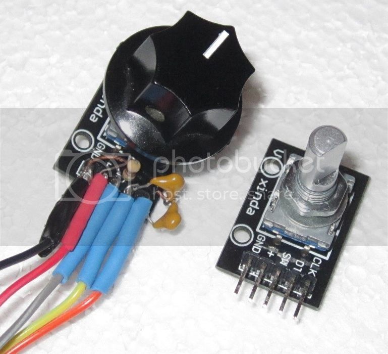
Usually, the inexpensive encoders I use have 5 pins: GND, Vcc, SW, SDTA, SCLK where the last two are the data and clock pins and SW is the switch activated by pressing the encoder shaft. This can be seen below:
The two caps are used to debounce the encoder and the resistor keeps the switch from floating. The code looks like:
ISR(PCINT2_vect) {
  unsigned char result = r.process();

  switch (result) {
    case 0:                                                 // Nothing done...
       return;

    case DIR_CW:                                      // Turning Clockwise, going to higher frequencies
       // Whatever a CW turn motion needs to do
       break;

    case DIR_CCW:                                    // Turning Counter-Clockwise
       // Whatever a CCW turn motion needs to do
      break;

    default:
      // Should never be here
      break;
  }

}
The code uses the Rotary library by Ben Buxton's GNU library. If you look at his examples in the library, I think you'll see how they work.
You are likely running into problems with the library syntax and the routines is uses to read the encoders. I usually write my own encoder code, and have not looked at the library in detail, but this scenario is likely.
Encoder myEnc(pin1, pin2);
Create an Encoder object, using 2 pins. You may create mulitple Encoder objects, where each uses its own 2 pins. The first pin should be capable of interrupts. If both pins have interrupt capability, both will be used for best performance. Encoder will also work in low performance polling mode if neither pin has interrupts.
In your first case, the library knows that pin1 is an interrupt pin and the second is not and most likely uses a routine which counts two of the four available quadrature states.
In your second case, it's not clear what routine the library uses, but is is using polling rather than interrupts and it may be missing counts.
If the direction of rotation is incorrect but the performance is good with the first pin declaration which has an interrupt on pin1 I think you could just invert the values produced by the encoder.
Is this application supposed to be some kind of rotary control selector knob, or counting how many times the wheel of your robot or RC car have turned ?
I would not approach these two problems the same way.
Usually, the inexpensive encoders I use have 5 pins: GND, Vcc, SW, SDTA, SCLK where the last two are the data and clock pins and SW is the switch activated by pressing the encoder shaft. This can be seen below:
This seems confusing. Are SDTA and SCLK the A and B pulse outputs ? Or something else ?
michinyon:
Is this application supposed to be some kind of rotary control selector knob, or counting how many times the wheel of your robot or RC car have turned ?
I would not approach these two problems the same way.
Thanks for everyone's comments.
The application is that the encoder is used to select the brightness of red, green, and blue lights in RGB leds, and a forth one for the speed of animations.
I could have used a pot, but spark fun had the nice rgb lighted encoders so I could make the knobs get brighter as I turned the dial... Also I like the feel of the intents.
Robin, I'm out of town but if the suggestions above don't work Ill right a new sketch to see if I can isolate the problem when I get back.
@michinyon: the pulse data is on the data line and the clock is used for its timing. The constructor for the encoder object uses the two interrupt pins on the Uno, 2 and 3. The reason I included Ben Buxton's name was so the interested reader could download his library and study the examples. They are pretty clear.