Arduino Mega - detection of rising edge and determination of signal period

Hi everyone, i have a little problem with the counter. I want to get the numerator value only in the rising edges. According to the code it is done, but sometimes the numerator values ​​vary by 30-40 units. For this reason, the final result of the calculated frequency varies by up to 15%. What could I correct or change to find the signal period based on the counter in input capture mode? I receive data on the computer side with the Realterm program and with the code written in python.
Arduino code:

#include <Arduino.h>

#define icpPin 49  
#define SerialDiode 13
#define sendingDiode 10


bool writeEnabled = true;

uint16_t isrData;
size_t isrValuesCount = 0;

struct __attribute__((packed)) Message {
  uint16_t header;
  uint16_t value;
};

Message msg{.header = 0x03};

void send_packet() {
  msg.value = isrData;
  Serial.write((uint8_t*)&msg, sizeof(msg));

}

ISR(TIMER4_CAPT_vect) 
{


  isrData = ICR4;
  TCNT4 = 0;
    
}

void prepareRegisters(){
 noInterrupts(); 

 TCCR4A = 0;
  TCCR4B = 0;
  TCNT4 = 0;
  TIMSK4 = 0;

  TIFR4 = _BV(ICF4) |  _BV(TOV4); 
  TCCR4B = _BV(CS40) | _BV(ICES4)| _BV(ICNC4);	   
  TIMSK4 = _BV(ICIE4) | _BV(TOIE4);          

  interrupts();

}
void setup() {

  Serial.begin(115200);

  pinMode(icpPin, INPUT);
  digitalWrite(SerialDiode, HIGH);
  prepareRegisters();
}

void loop() {
  if (writeEnabled) {
    send_packet();
    digitalWrite(sendingDiode, HIGH);
  } else {
    digitalWrite(sendingDiode, LOW);
  }


  delay(200);

}

Python code: ( i use pyserial library )

 def readValue(self):
        try:

            headerByte = self.connection.read(2)

            if (headerByte == b'\x03\x00'):
                payload = self.connection.read(2)

                value = struct.unpack('<H', payload)[0]
                print(value)
                return value
            return None

output from VS code terminal:

1567
1554
1568
1568
1568
1568
1568
1568
1568
1568
1568
1567
1563
1553
1560
1564
1566
1564
1565
1566
1567
1566
1555
1566
1565
1567
1567
1567
1568
1564
1557
1567
1557
1567
1565
1567
1568
1567
1567
1568
1553
1567
1567
1568
1567
1568
1561
1568
1568
1568
1559
1565
1557
1567
1568
1562
1567
1566
1568
1558
1567
1568
1568
1567
1561
1567
1567
1556
1560
1566
1560
1568
1568
1568
1567
1560
1562
1568
1567
1567
1567
1564
1568
1566
1565
1568
1568
1567
1568
1568
1567
1567
1567
1567
1568
1567
1568
1567
1564
1556
1567
1567
1567
1568
1567
1565
1568
1563
1567
1568
1566
1566
1530
1567
1568
1567
1567
1568
1566
1568
1567
1564
1567
1567
1567
1567
1566
1554
1567
1568
1558
1568
1567
1566
1568
1563
1566
1567
1565
1556
1568
1563
1568
1568
1561
1568
1567
1568
1568
1567
1565
1565
1567
1560
1556
1565
1568
1568
1568
1558
1567
1556
1567
1565
1568
1566
1567
1561
1565
1555
1567
1568
1566
1567
1564
1564

1566
1566
1567
1567
1568
1568
1567
1567
1568
1568
1568
1568
1567
1567
1567
1567
1557
1557
1563
1563
1568
1568
1568
1568
1567
1567
1565
1565
1568
1568
1558
1558
1568
1568
1566
1566
1568
1568
1566
1566
1566
1566
1568
1568
1567
1567
1566
1566
1568
1568
1565
1565
1568
1568
1567
1567
1563
1563
1567
1567
1556
1556
1557
1557
1565
1565
1468
1468
1566
1566
1568
1568
1568
1568
1560
1560
1554
1554
1561
1561
1567
1567
1567
1567
1566
1566
1563
1563
1553
1553
1563
1563
1567
1567
1568
1568
1566
1566
1567
1567

1565
1557
1564
1561
1567
1567
1566
1566
1568
1567
1567
1567
1567
1564
1568
1561
1565
1564
1565
1561
1567
1568
1568
1567
1567
1563
1567
1567
1568
1567
1567
1568
1568
1555
1561
1558
1562
1565
1567
1564
1567
1567
1568
1568
1567
1567
1567
1558
1567
1567
1567
1568
1567
1567
1568
1561
1557
1564
1568
1567
1568
1567
1567
1554
1565
1568
1567
1568
1568
1568
1568
1553
1567
1568
1567
1566
1568
1568
1568
1567
1567
1568
1567
1568
1553
1566
1567
1567
1567
1563
1568
1567
1566
1568
1560
1567
1561
1560
1564
1567
1567
1567
1560
1567
1568
1565
1567
1563
1567
1568
1568
1567
1470
1568
1568
1567
1564
1560
1568
1567
1567
1562
1564
1567
1568
1568
1567
1567
1566
1567
1567
1567
1566
1568
1567
1556
1568
1568
1567
1567
1568
1553
1567
1568
1556
1568
1567
1568
1568
1557
1567
1568
1568
1567
1567
1565
1567
1566
1568
1567
1568
1567
1568
1565
1567
1553
1556
1567
1568
1568
1567
1568
1568
1567

Please help

isrdata should be declared volatile.

You shouldn't enable an interrupt and not define a handler for it.

In my calculations the frequencies vary by about 2-3%, I don't know how you get to 15%.

My guess is that the time keeping interrupt (timer0) may cause the variations. As you don't need that functionality you can disable timer0. Another cause could be the serial interrupt which is also higher prioritized than timer4 capture interrupts. This may be avoided by using timer 2 instead.

thanks for response. So at first i will change variables to volaitle. But why timer 0 could give to me this problems ? About code, could you show me example about your idea? Im trully new in this and i dont wanna do another mistakes.

you mean noInterrupts(); and interrupts(); ? Are these methods not required to correctly set the interrupts?

No, in your code you enable the overflow interrupt for timer 4 (TOIE4) but you don't define a handler for that interrupt.

Only variables used in interrupt handlers and normal code must be declared volatile.

Because timer 0 is used for Arduino time keeping (millis(), delay(), etc.) and timer 0 interrupts are higher prioritized than timer 4 interrupts. Additionally interrupts are disabled during interrupt handlers by default.

I don't think the Mega or any old 8-bit AVR support interrupt priorities. They are all on the same priority levels

No, in your code you enable the overflow interrupt for timer 4 (TOIE4) but you don't define a handler for that interrupt.

I miss this part in my code.Thanks.
Here is new code but with previous errors:


#include <Arduino.h>

#define icpPin 49  
#define SerialDiode 13
#define sendingDiode 10
#define getcharDiode 11

bool writeEnabled = true;

volatile uint16_t isrData;
volatile uint16_t overflow;


struct __attribute__((packed)) Message {
  uint16_t header;
  uint16_t value;
};

Message msg{.header = 0x01};

void send_packet() {
  msg.value = isrData;
  Serial.write((uint8_t*)&msg, sizeof(msg));

}
ISR(TIMER4_OVF_vect){
  overflow++;
}
ISR(TIMER4_CAPT_vect)  
{

  isrData = ICR4;
  TCNT4 = 0;

    
}

void prepareRegisters(){

 TCCR4A = 0;
  TCCR4B = 0;
  TCNT4 = 0;
  TIMSK4 = 0;

  TIFR4 = _BV(ICF4) |  _BV(TOV4); 
  TCCR4B = _BV(CS40) | _BV(ICES4)| _BV(ICNC4);	   
  TIMSK4 = _BV(ICIE4) | _BV(TOIE4);          

  interrupts();

}
void setup() {
  // put your setup code here, to run once:
  Serial.begin(9600);

  pinMode(icpPin, INPUT);
  digitalWrite(SerialDiode, HIGH);
  prepareRegisters();
}

void loop() {
  if (writeEnabled) {
    send_packet();
    digitalWrite(sendingDiode, HIGH);
  } else {
    digitalWrite(sendingDiode, LOW);
  }
}

I try even plot data and ther is result: In OX is number of meansure data, in OY is value what i get from arduino.


most of data is about 1566 but sometimes just get a little lower.

The datasheet says something different:

The lowest addresses in the program memory space are by default defined as the Reset and
Interrupt Vectors. The complete list of vectors is shown in “Interrupts” on page 105. The list also
determines the priority levels of the different interrupts. The lower the address the higher is the
priority level. RESET has the highest priority, and next is INT0 – the External Interrupt Request
0.

Post the results you get if you disable the timer 0 interrupts:

TIMSK0 = 0;

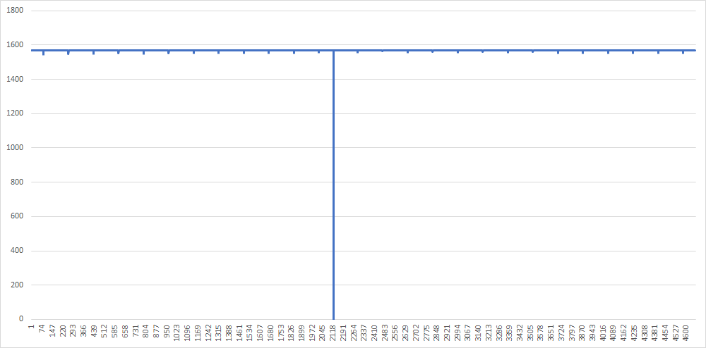
This is output from my code. Signal used to test - 10kHz
If you count frequency from this output, you will see this data is a little invalid.
obraz
Maybe instead of clear TCNT4 when edge occurred, just sending tiler state to PC and then count period with simple math?

For counting signal edges, you should be using the T-pins instead of ICP. It's much easier to use if your signal is less than 65000 kHz

Here's an example of using pin PL2 (for TIMER5) for signal input and counting the high edges every second

volatile uint8_t ONEHZ = 0;
volatile uint16_t cycles = 0;


// 1 Hz ticker from TIMER1
ISR(TIMER1_COMPA_vect)
{
	ONEHZ = 1;
	// stop timer 5
	TCCR5B = 0;
	cycles = TCNT5;
	TCNT5 = 0;
	TCCR5B = 1<<CS52 | 1<<CS51 | 1<<CS50;
}

void setup()
{
    Serial.begin(9600);

	/*********************
	Enable Counter on T5 pin
	rising edge (PL2)
	*********************/
	// input
	DDRL &= ~(1<<PINL2);
	
	// normal counting mode
	TCCR5A = 0;
	TCCR5C = 0;
	TIMSK5 = 0;
	TCNT5 = 0;
	TCCR5B = 1<<CS52 | 1<<CS51 | 1<<CS50;
	

	/*********************
	Generate 1 Hz timebase
	CTC mode
you can use millis() instead if you
want to
	*********************/
	TCCR1A = 0<<WGM11 | 0<<WGM10;
	TCCR1B = 0<<WGM13 | 1<<WGM12 | 0<<CS12  | 0<<CS11 | 0<<CS10;
	// zero out counter value
	TCNT1 = 0;
	// set TOP value
	OCR1A = 62500 - 1;
	// enable interrupt on OCR1A compare
	TIMSK1 = 1<<OCIE1A;
	// start timer1
	TCCR1B = 0<<WGM13 | 1<<WGM12 | 1<<CS12  | 0<<CS11 | 0<<CS10;
}

void loop()
{
	if(ONEHZ)
	{
		ONEHZ = 0;
		//serial.print(cycles);
	}
}


Use this pin

Thanks for response. Its nice idea but in my project i need analyze singals in range 100 Hz - 100kHz :confused:

The reason why I said 65000 Hz limit is I made the time base 1 Hz. The TCNT5 is a 16 bit number so it overflows at 65535+

You can change the "update" rate to 0.5 second and you can measure signal up to 131 kHz

Changing the update rate to 100 ms and you can count edges in the 650 kHz

All you need to change is the OCR1A

Change that to

	OCR1A = 31250 - 1;

and you can measure up to 131 kHz and it will print out the value every 500 ms

I dont even know about that, thanks :smiley:
One question, if i had non-periodic signals which varies in the range of e.g. 10kHz 100kHz, will this method be very accurate?

It will average at the sampling rate. So if the sampling is at 0.5 seconds, then it's the average frequency for that time. You can change the sampling to say 100 ms and you will get better resolution since it will calculate the frequency value every 100 ms.

There's no stopping you from calculating the frequency every 1ms but then how do you display that data since serial.print takes in the tens of ms to print data out. Unless you want to save the data for processing later, but then again, if you are collecting 1000 measurements a second, you need a fast storage or large amount of SRAM

So if serial.print takes a little amount of time, maybe faster way will be use make code in C and use USART ? This make any sense ?

Just for example, lets say your serial speed is 9600 (using Serial.begin(9600)).

To print out "hello world" would take around ~10ms to print. If you are collecting data at 1000 Hz or 1 each ms, you obviously can't print out all the data. To be able to print all the collected the data out, you have to collect it at around every 15 ms or so. You can make serial faster but there's a limit in hardware. You might be able to print at 1 Mbps...

Thanks a lot, i will test that for sure :smiley:
Could you look on my second question ? Its almost the same but i dont know why timer give this output.
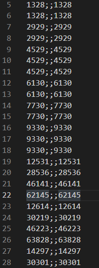
In pic is raw data from arduino. left column (ICR4L and ICR4h packed, right column ICR4)

This is wrong. It takes a few µs to print that because the print will write the characters into a buffer. The first byte will be written into a hardware register to send it out and once it was sent an interrupt handler will get the next byte from the buffer and so on until the whole content is sent. These interrupts (to get another byte from the buffer) may influence your measuring result.

No, you wont' get it much faster if you do it yourself. You can disable the interrupt and do polling in the loop which may increase the measuring accuracy but may make the data transfer much slower. You definitely should increase the baud rate.

Which one? The one I already answered but you don't react?

What happens if you keep sending data to the UART buffer faster than the hardware UART can print?

If I increase the baud rate to 38400 for example, I will have the data without errors, but with a higher value I will get a lot of errors such as reordering the transmitted bits.

this one --> Pyserial and Arduino Input Capture