OK sorry newb here but am looking for a few basic details. I have the above board sat on my Arduino board. My project is fan controllers for my racing sim rig.
I have 2 120mm PC fans with 3pin connectors, ive been unable to work out or find a diagram which gives the details on all the connectors on the Motor shield board. Can i connect these fans to the board to one of these connectors, i have ordered some Dupont connectors in case i can't.
Also the arduino uno is currently plugged into a substantial 12v 3A supply will that power these outputs also via the joined connections?
Any tips appreciated! I am using Simlab software which i believe has various Arduino profiles already.
Your power supply and the fans are connected to screw terminals on the shield. You can remove the 3-pin connector from fans (or use 22AWG solid core wire as jumper) and just ignore the yellow wire.
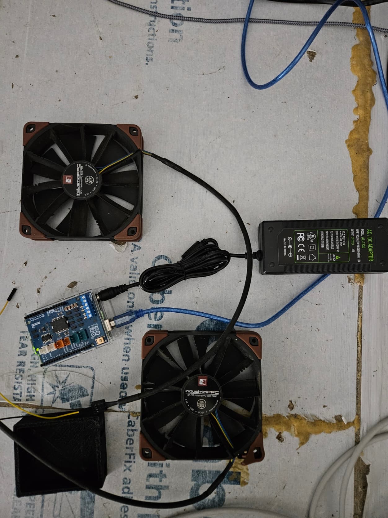
Thankyou so much for replying but this isn't my board, mine looks like this which is sat on top of the arduino uno. I have a 12v 3amp supply plugged into the Arduino Uno board which i believe feeds power via piggy back pins power into the Motor shield board powering that also?
See the Rev3 schematic diagram here for my Motor shield board.
I intend to control 2 120cm fans visible in the photo
Woke up thinking about this, my fans are 4pin and this is all about varying the speed as this for Simhub a driving sim so the wind speed varies.
Therefore we need to control the fan speed via PWM. So thats 3 connections.
Well, that would make things quite different, and you don't need the motor shield.
In principle, you can connect the fan PWM to any Arduino pin that supports PWM. However, the stock code may not output the right PWM frequency; a particular frequency may be required.
PWM Frequency: target frequency 25 kHz, acceptable operational range 21 kHz to 28 kHz.
I guess they chose that frequency partly to be outside the range of human hearing. However, I doubt that a fan would reject frequencies outside that range. Often the PWM is fed into a charge pump and produces a voltage for the motor driver, so while a different input frequency may be "out of spec", it is unlikely to just not work.
As I happened to have a faulty fan I just pulled which I don't mind breaking, I thought I would see if the standard analogWrite() would work. Well, it does work, at least the fan goes slower or faster.
You may get a less linear response with a lower frequency, or maybe also audible noise (which my aged ears would not hear :)). However, the fan response is not very linear anyway, so you would probably develop your own "map" in any case.
It may also depend on the fan you use, but my conclusion is that a frequency outside the "official spec" may well still work, at least to a reasonable degree.