hello and good day everyone ,
I am currently working on a project involving an Arduino Nano, a TFT display, and an SD card logger. Individually, both the SD card and TFT display codes function without issues. However, when I attempt to merge these codes, the TFT display begins to blink continuously and fails to show any readings.
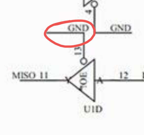
From my understanding, this could be a conflict in the SPI communication between the two devices (pin 11, 13). I would greatly appreciate any guidance or resources you could provide to resolve this issue. If there are any code adjustments that could facilitate the simultaneous operation of both the TFT display and the SD card logger on the Arduino Nano, it would be immensely helpful.
Thank you for your time and assistance.
Physical connections
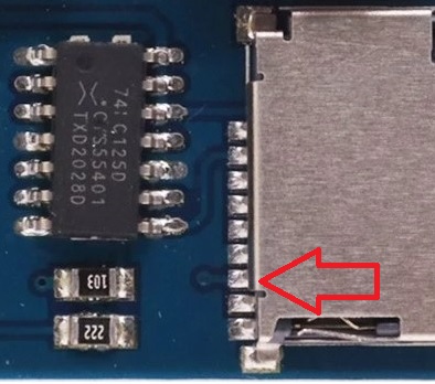
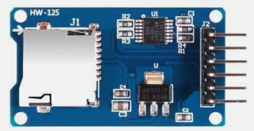
Data Logging Module - RTC and Micro SD Card
SD card attached to SPI bus as follows:
- VCC= 5V
- GND=GND
- MOSI - pin 11<====
- MISO - pin 12
- CLK - pin 13<====
- CS - pin 4
DS1307 real-time clock - SCL = A5
- SDA = A4
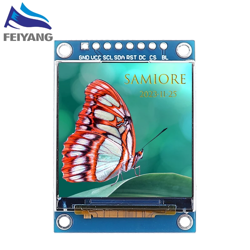
ST7735 TFT DISLAY 1.8’ 128X160 - VCC= 5V
- GND=GND
- SCL=13 <====
- SDA=11 <====
- RST=9
- DC=8
- CS=10
- BLK=NC
Project video
https://drive.google.com/file/d/1hRAy3ma_BDEmvnsBAWR2LLN-cfsrluNi/view?usp=drive_link

/**************************************************************************
 Arduino interface with ST7735 color TFT (128x160 pixel) display and
 DHT11 digital humidity and temperature sensor.
  **************************************************************************/
#include <Adafruit_GFX.h>     // include Adafruit graphics library
#include <Adafruit_ST7735.h>  // include Adafruit ST7735 TFT library
#include <DHT.h>              // include DHT library
#include <SD.h>
#include <RTClib.h>  // Real Time Clock Library

/**********************TFT 1.8 Dislay*********************************/
#define TFT_RST 9  // TFT RST pin is connected to arduino pin 9
#define TFT_CS 10  // TFT CS  pin is connected to arduino pin 10
#define TFT_DC 8   // TFT DC  pin is connected to arduino pin 8
// nano SCL->13, SDA->11
// initialize ST7735 TFT library
Adafruit_ST7735 tft = Adafruit_ST7735(TFT_CS, TFT_DC, TFT_RST);

/**********************DHT Sensor*************************************/
#define DHTPIN 2             // DHT11 data pin is connected to Arduino digital pin 2
#define DHTTYPE DHT11        // DHT11 sensor is used
DHT dht11(DHTPIN, DHTTYPE);  // initialize DHT library

/********************* SD Card & RTC ********************************/
const int chipSelect = 4;  // Sd card pin selection
File myFile;
char filename[] = "yyyymmdd.txt";  // filename (without extension) should not exceed 8 chars
/*
SD card attached to SPI bus
CS connected to pin 4 for Nano
*/
RTC_DS1307 rtc;  //call library for clock

/******************* Update Frequently *****************************/
const unsigned long eventInterval = 1000;  //Time interval
unsigned long previousTime = 0;


void setup(void) {
  dht11.begin();                  // initialize DHT11 sensor
  pinMode(4, OUTPUT);            // make sure that the default SD chip select pin is set to output, even if you don't use it:

  tft.initR(INITR_BLACKTAB);     // initialize a ST7735S chip, black tab
  tft.fillScreen(ST7735_BLACK);  // fill screen with black color
  tft.setTextColor(ST7735_GREEN, ST7735_BLACK);

  // see if the card is present and can be initialized:
  if (!SD.begin(chipSelect)) {
    tft.setCursor(30, 65);
    tft.print("Card failed");
    tft.setCursor(15, 85);
    tft.print(" or not present");

    while (1)
      ;  // don't do anything more:
  }
  tft.setCursor(10, 65);
  tft.print("card initialized...");
  delay(2000);

  tft.fillScreen(ST7735_BLACK);                        // fill screen with black color
  tft.drawRoundRect(0, 0, 128, 130, 5, ST77XX_BLUE);   //Draw round rectangular (C,R,W,H,ROUND, COLOR )
  tft.drawFastHLine(0, 45, tft.width(), ST7735_BLUE);  // draw horizontal blue line at position (0, 45)
  tft.drawFastHLine(0, 88, tft.width(), ST7735_BLUE);  // draw horizontal blue line at position (0, 88)

  tft.setTextColor(ST7735_YELLOW, ST7735_BLACK);  // set text color to yellw and black background
  tft.setTextSize(1);                             // text size = 1
  tft.setCursor(16, 7);                           // move cursor to position (16, 7) pixel
  tft.print("SD Data Logger");

  tft.setTextColor(ST7735_GREEN, ST7735_BLACK);  // set text color to green and black background
  tft.setCursor(32, 53);                         // move cursor to position (32, 53) pixel
  tft.print("TEMPERATURE");

  tft.setTextColor(ST7735_GREEN, ST7735_BLACK);  // set text color to orange and black background
  tft.setCursor(42, 96);                         // move cursor to position (42, 96) pixel
  tft.print("HUMIDITY");
  tft.setTextSize(2);  // text size = 2

  tft.drawRoundRect(0, 132, 128, 28, 5, ST77XX_BLUE);  //Draw round rectangular (C,R,W,H,ROUND, COLOR )
  tft.setTextColor(ST77XX_WHITE, ST77XX_BLACK);        // set text color to green and black background
  tft.setCursor(4, 140);                               // move cursor to position (COLUMN 4, RAW 140) pixel
  tft.print("PKEEE, USM");
}

// main loop
void loop() {

  /*******Reading temperature or humidity takes about 250 milliseconds*****/
  // read humidity
  byte humi = dht11.readHumidity();
  // read temperature
  byte temp = dht11.readTemperature();
  // Compute heat index in Celsius (isFahreheit = false)
  float hic = dht11.computeHeatIndex(temp, humi, false);

  /**************************Data Logging ************************************/
  unsigned long currentTime = millis();
  if (currentTime - previousTime >= eventInterval) {
    logData(humi, temp, hic);
    previousTime = currentTime;
  }

  // print temperature (in °C)
  tft.setTextColor(ST7735_RED, ST7735_BLACK);  // set text color to red and black background
  tft.setCursor(42, 68);
  tft.print(temp);
  tft.drawCircle(77, 70, 2, ST7735_RED);  // print degree symbol ( ° )
  tft.setCursor(83, 68);
  tft.print("C");

  // print humidity (in %)
  tft.setTextColor(ST7735_CYAN, ST7735_BLACK);  // set text color to cyan and black background
  tft.setCursor(44, 110);
  tft.print(humi);
  tft.setCursor(79, 110);
  tft.print("%");
  delay(1000);
}
/**************************Data Logging ************************************/
void logData(byte humi, byte temp, float hic) {

  DateTime now = rtc.now();
  int year = now.year();
  int month = now.month();
  int day = now.day();

  // update filename
  filename[0] = (year / 1000) + '0';
  filename[1] = ((year % 1000) / 100) + '0';
  filename[2] = ((year % 100) / 10) + '0';
  filename[3] = (year % 10) + '0';

  filename[4] = (month / 10) + '0';
  filename[5] = (month % 10) + '0';

  filename[6] = (day / 10) + '0';
  filename[7] = (day % 10) + '0';

  // open the file. note that only one file can be open at a time, so you have to close this one before opening another.
  myFile = SD.open(filename, FILE_WRITE);
  if (myFile) {  // if the file is available, write to it:
    myFile.print(now.year(), DEC);
    myFile.print('/');
    myFile.print(now.month(), DEC);
    myFile.print('/');
    myFile.print(now.day(), DEC);
    myFile.print(",");
    myFile.print(now.hour(), DEC);
    myFile.print(':');
    myFile.print(now.minute(), DEC);
    myFile.print(':');
    myFile.print(now.second(), DEC);

    myFile.print(",");  // delimiter between timestamp and data

    myFile.print("Humidity(%):");
    myFile.print(",");
    myFile.print(humi);
    myFile.print(",");
    myFile.print("Temperature(°C):");
    myFile.print(",");
    myFile.print(temp);
    myFile.print(",");
    myFile.print("Heat index(°C):");
    myFile.print(",");
    myFile.println(hic);
    myFile.close();
  }
}
// end of code.