I am currently working on my first project with Arduino and I have some problems. I am trying to get some readings from my temperature sensor (TMP117) board SEN15805 but I can not see nothing on the monitor or plotter.
My schematic looks like this:
The board has a ready Arduino Library which I installed and everytime I try to execute some of the examples I get nothing as a result.
To be more precise I give you the code I upload for "Basic Reading":
/******************************************************************************
  Example1_BasicReadings.ino
  Example for the TMP117 I2C Temperature Sensor
  Madison Chodikov @ SparkFun Electronics
  May 29 2019
  ~

  This sketch configures the TMP117 temperature sensor and prints the
  temperature in degrees celsius and fahrenheit with a 500ms delay for
  easier readings.

  Resources:
  Wire.h (included with Arduino IDE)
  SparkFunTMP117.h (included in the src folder) http://librarymanager/All#SparkFun_TMP117

  Development environment specifics:
  Arduino 1.8.9+
  Hardware Version 1.0.0

  This code is beerware; if you see me (or any other SparkFun employee) at
  the local, and you've found our code helpful, please buy us a round!

  Distributed as-is; no warranty is given.
******************************************************************************/

/*
  NOTE: For the most accurate readings:
  - Avoid heavy bypass traffic on the I2C bus
  - Use the highest available communication speeds
  - Use the minimal supply voltage acceptable for the system
  - Place device horizontally and out of any airflow when storing
  For more information on reaching the most accurate readings from the sensor,
  reference the "Precise Temperature Measurements with TMP116" datasheet that is
  linked on Page 35 of the TMP117's datasheet
*/

#include <Wire.h>            // Used to establish serial communication on the I2C bus
#include <SparkFun_TMP117.h> // Used to send and recieve specific information from our sensor

// The default address of the device is 0x48 = (GND)
TMP117 sensor; // Initalize sensor

void setup()
{
  Wire.begin();
  Serial.begin(115200);    // Start serial communication at 115200 baud
  Wire.setClock(400000);   // Set clock speed to be the fastest for better communication (fast mode)

  Serial.println("TMP117 Example 1: Basic Readings");
  if (sensor.begin() == true) // Function to check if the sensor will correctly self-identify with the proper Device ID/Address
  {
    Serial.println("Begin");
  }
  else
  {
    Serial.println("Device failed to setup- Freezing code.");
    while (1); // Runs forever
  }
}

void loop()
{
  // Data Ready is a flag for the conversion modes - in continous conversion the dataReady flag should always be high
  if (sensor.dataReady() == true) // Function to make sure that there is data ready to be printed, only prints temperature values when data is ready
  {
    float tempC = sensor.readTempC();
    float tempF = sensor.readTempF();
    // Print temperature in °C and °F
    Serial.println(); // Create a white space for easier viewing
    Serial.print("Temperature in Celsius: ");
    Serial.println(tempC);
    Serial.print("Temperature in Fahrenheit: ");
    Serial.println(tempF);
    delay(500); // Delay added for easier readings
  }
}
I have installed from the board manager the Arduino Mbed OS boards to use Arduino Nano 33 BLE and I can see my Arduino in COM5, when I upload the code the COM5 is lost and I can only see arduino in COM4, I change the ports and when I open the Serial Monitor I get nothing as a result.
Am I doing something wrong? I have the same problem with other different boards, such as MAX30105 from Pimoroni and GPS Neo 6M from Ublox. Was not the examples supposed to work just by uploading them? Is there an explanation why after I upload the code it changes ports?
I have tried connecting it to USB 3/2 both in the front and the back of my desktop.
Any help would be huge!
That is expected behavior. Most of the newer Arduinos have native USB while the older models have a separate chip handling USB. The Arduino has two USB endpoint configurations. One is created by the bootloader for programming and one is used while your sketch is running. You can switch between the modes by single click reset for normal mode and double click reset for bootloader mode. Windows can tell the difference between the two configurations and therefore assigns two COM port numbers.
Arduinos with native USB ignore the baudrate value.
I recommend you add a while(!Serial); after Serial.begin. This will make the sketch wait for you to connect and open the Serial Monitor or Serial Plotter window in the IDE. This will ensure you will see the first prints.
The Arduino world supports many different devices, all of the have their own specialty and the software runs bare metal. It is not possible to cover all cases except for some very trivial sketches.
Thank you very much for your answer.
By adding the while(!Serial); line on my code I could see results in the serial monitor. Everytime I got the Serial.println("Device failed to setup- Freezing code."); so I ran an I2C scanner and I saw that my arduino nano 33 ble could not see the I2C connection.
I checked all the wires and they seem fine, I read that in the Arduino Nano 33 BLE there is a problem with the I2C function, is this true?
1)Is Wire library working as an I2C Slave? · Issue #32 · arduino/ArduinoCore-nRF528x-mbedos · GitHub
2)Wire library, i2C NOT WORKING · Issue #37 · arduino/ArduinoCore-nRF528x-mbedos · GitHub
When I try to install from the Board Manager the other Arduino Mbed OS it says DEPRECATED, does this mean that it will not work?
I do not believe that to be the case. My BME-280 works without any issue.
As for I2C slave support. I do not see a need for that in most cases. The Arduino is supposed to be the major device for BLE applications. In that case it will be the master. If you must connect it to another device that has a master role, you can use other interfaces e.g., UART.
Deprecated just means, you can continue to use this packet if you are happy that there will be no further improvements. If it is convenient for you, please use the new version. I your cases just search for BLE in the board manager. You should see another board package "Arduino Mbed OS Nano Boards", current version 2.3.1. Use that one. The Arduino team split the package to make it smaller and only support the Nano sized boards. The Portenta H7 got its own board package.
You can install both the new and deprecated board package and then switch between the two. If you never used the old one, there is no need for you to do that.
It looks like you have a separate power supply for the sensor. Did you connect the two grounds?
I am really lost, cause I try the same things over and over again and I get no results. I have tried changings the wires, I have checked many times that I connect the correct pins (SDA to SDA and SCL to SCL) and the board seems to get powered just fine (led is open).
Edit:
By running this code:
#include <Wire.h>            // Used to establish serial communication on the I2C bus
#include <SparkFun_TMP117.h> // Used to send and recieve specific information from our sensor

// The default address of the device is 0x48 = (GND)
TMP117 sensor; // Initalize sensor

void setup()
{
  Wire.begin();
  Serial.begin(115200);    // Start serial communication at 115200 baud
  while(!Serial);
  Wire.setClock(400000);   // Set clock speed to be the fastest for better communication (fast mode)
  Serial.print("Current Device Address: ");
  Serial.println(sensor.getAddress(), HEX); // Prints the current address of the device in Hex
  Serial.println("TMP117 Example 1: Basic Readings");
  if (sensor.begin() == true) // Function to check if the sensor will correctly self-identify with the proper Device ID/Address
  {
    Serial.println("Begin");
  }
  else
  {
    Serial.println("Device failed to setup- Freezing code.");
    while (1); // Runs forever
  }
}

void loop()
{
  // Data Ready is a flag for the conversion modes - in continous conversion the dataReady flag should always be high
  if (sensor.dataReady() == true) // Function to make sure that there is data ready to be printed, only prints temperature values when data is ready
  {
    float tempC = sensor.readTempC();
    float tempF = sensor.readTempF();
    // Print temperature in °C and °F
    Serial.println(); // Create a white space for easier viewing
    Serial.print("Temperature in Celsius: ");
    Serial.println(tempC);
    Serial.print("Temperature in Fahrenheit: ");
    Serial.println(tempF);
    delay(500); // Delay added for easier readings
  }
}
It is the same code, but I added the following lines:
Serial.print("Current Device Address: ");
Serial.println(sensor.getAddress(), HEX); // Prints the current address of the device in Hex
I get the following:
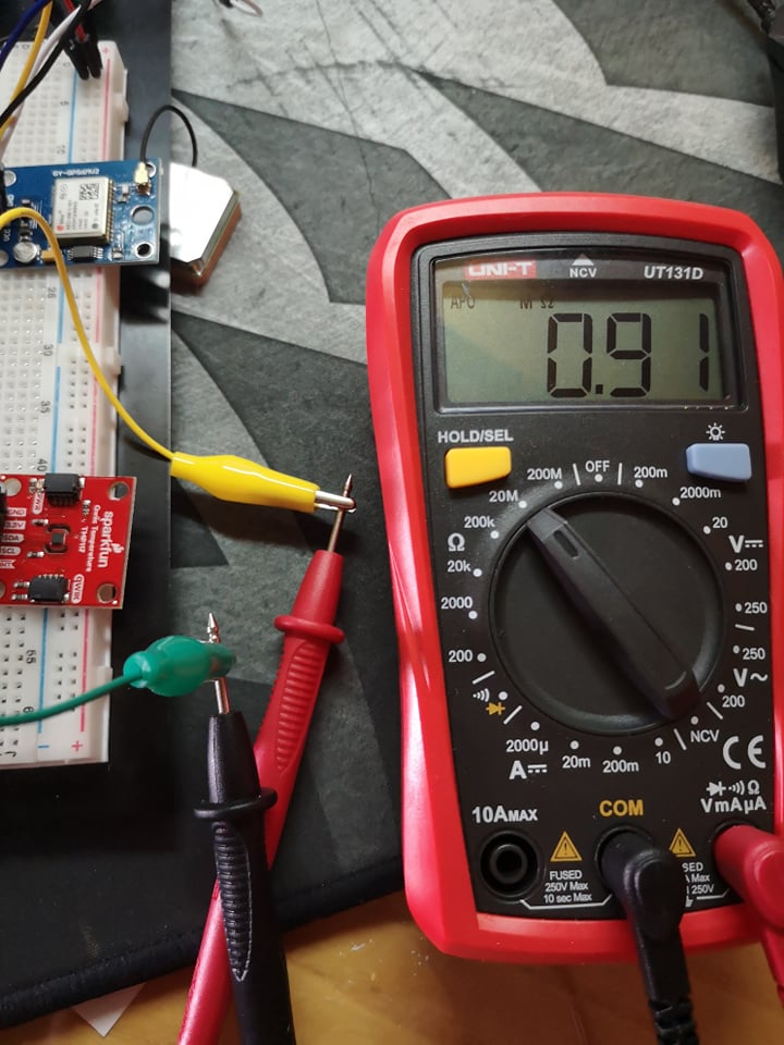
When you measure voltages you need to measure on the pin of the board you are using. You seem to be measuring on the bread board connector.
Also, remove all power and use the continuity function to see if you have a connection between the I2C lines on the board and on the Arduino pin.
Again with the power off measure the resistance between the 3V3 line and the I2C lines. You should see the pull up resistor's value.
@Grumpy_Mike Yes I was measuring from the bread board connector, I measured again directly from the pins and I get 3.32V.
Then I tried to measure the resistance as you suggested and I got some weird results:
Between the 3.3V pin and the SCL I got:
Unfortunately due to summer/covid restrictions I do not have access to my University lab so I can not use an oscilloscope.
edit:
I have posted my problems on the Sparksfun forum also and one user suggested to solder the headers and that wires through holes do not work, is this a thing?
Could I not solder wires through the holes without putting the headers and getting good results?
Of course you can. Wires have been soldered onto trough hole PCBs hundred of billions of times. Wires can create issues, especially with a bus like I2C (HIGH is passive driven by pull-up resistors). So, keep SDA and SCL spaced apart and as short as possible.
This could mean
Could I, not solder wires through the holes, without putting the headers and getting good results?
Meaning just wrap the wires round and not solder them.
Or it could mean
Could I not, solder wires through the holes without putting the headers and getting good results?
Meaning, actually soldering wires direct to the holes.
Yes you are totally right. English is not my native language and I still mess it up.
My question was the second one, actually solder the wires direct to the holes.
But currently I have NOT solder anything yet because I wanted to check if everything works properly before I decide which wire (length) I will use to fit my needs for the project. Is this a good reason why I get random measurements on the resistances on the I2C line? That only wrapping the wires on the holes without solder gives me all this problems?
I will try to solder the headers to test it out and then move to soldering the wires on the holes to check what kind of measurements I get and If my Nano 33 BLE can see any I2C connection.
Thanks for your answers!
So after soldering the wires through the holes the I2C scanner can see the device at the address 0x48 and I get my reading just fine (for 1/2 boards I have). It seems that the connection between the wires and the SDA/SCL pin was not good at all.
Thank you for your time and answers, you really helped me a lot!