Actually it takes 4 clockcycles

1 Like
I have tried to make a test to evaluate this internal resistor in my current Arduino Nano. I measured a digital output from the Arduino by connecting it to an analog input pin. Then I shifted the digital output for each analog value measured. In this way I tried to look for a tail of the measured value due to the RC time constant. I repeated measurement 20 times for each used sample time and prescaler value. This is the measured data values:

The rest revealed no indication of a tail.
I measured the DC voltage of a constant logical signal on the output pin used:
Output set to LOW caused a voltage of 0.3 mV above GND voltage.
Output set to HIGH caused a voltage of 9.3 mV below the approx. +5V supply voltage.
Therefore the the high measurements is not expected to be 1023, but a bit below.
I think it is reasonable to say, that the posible tail is below 1 LSB. 1 LSB can be achieved by 6.9 time constants. The highest ADC clock was 2 MHz, and it makes the sample hold time to be 0.75 us. The actual time constant should in my case be below 0.75 / 6.9 = 0.11 us, and therefore this test verify this internal resistance to be below 8 kohm for my one Arduino Nano with the 328P processor.
This is the test program used:
// This program is supposed to test the time constant of the ADC sample hold circuit of a Arduino Nano.
// The analog value of a digital shifting digital output is measured, and you look for the tail of the RC constant
// The ADC clock frequency is changed, to see the influence of a shorter sample hold time.
// The sample rate may also be changed.
// data storage can be 750 of integers (2 bytes) of 10 bit ADC values.
// Afterwords, the date is written to serial monitor. Excel got a Datastreamer add, that is activated and used.
// First a sample_time of 200 us is used with 10 alternations of digital pin for each prescaler value of 128, 64, 32, 16, 8.
// Then a sample time of 50 us and 32, 16, 8.
const int analog_input_pin= A3;
const int pin_out_to_to_be_measured = PD6;
const int max_index_store = 750;
const int print_loop_delay = 10; //At 5 Excel Datastreamer fails. At 6 it is OK. 7 is chosen to be at bit more safe.
int analog_input = 0;
int index_store = 0;
int index_store_used = 0;
int ADC_values_store[max_index_store];
long int micros_trig;
long int micros_start;
long int micros_end;

// This function sets the ADC-clock prescaler value of the Rev 3 Arduino Nano AD-converter.
// Check that the AD-converter is not busy before you call this function.
// The adc clock frequency will be the main clock frequency of normally 16 Mhz divided by the parameter value.
// The accepted parameter values are 2, 4, 8, 16, 32, 64, or 128. Otherwise the prescaler is set to 128.
void set_adc_prescaler(int divider_value){
  byte adcreg_code = 0x07;
  switch (divider_value) {
  case 2: adcreg_code = 0x01; break;
  case 4: adcreg_code = 0x02; break;
  case 8: adcreg_code = 0x03; break;
  case 16: adcreg_code = 0x04; break;
  case 32: adcreg_code = 0x05; break;
  case 64: adcreg_code = 0x06; break;
  default: adcreg_code = 0x07;
  }
 ADCSRA = (ADCSRA & 0xF8) | adcreg_code;
}

// the setup function runs once when you press reset or power the board
void setup() {
  // initialize serial communication at 9600 bits per second:
  Serial.begin(9600);
  pinMode(analog_input_pin, INPUT);
  pinMode(pin_out_to_to_be_measured, OUTPUT);
  digitalWrite(pin_out_to_to_be_measured, LOW);
  delay(100);
  Serial.println();
  Serial.println("Test started!");
  set_adc_prescaler(128);
  delay(100);
  analog_input = analogRead(analog_input_pin);
  index_store = 0;
  index_store_used = 20;
  micros_trig = micros() + 200;
  micros_start = micros_trig;
  while (index_store < index_store_used) {
    digitalWrite(pin_out_to_to_be_measured, HIGH);
    while (micros() < micros_trig) {}
    analog_input = analogRead(analog_input_pin);
    ADC_values_store[index_store] = analog_input;
    index_store ++;
    micros_trig = micros_trig + 200;
    digitalWrite(pin_out_to_to_be_measured, LOW);
    while (micros() < micros_trig) {}
    analog_input = analogRead(analog_input_pin);
    ADC_values_store[index_store] = analog_input;
    index_store ++;
    micros_trig = micros_trig + 200;
    }
  set_adc_prescaler(64);
  delay(10);
  index_store_used = index_store_used + 20;
  while (index_store < index_store_used) {
    digitalWrite(pin_out_to_to_be_measured, HIGH);
    while (micros() < micros_trig) {}
    analog_input = analogRead(analog_input_pin);
    ADC_values_store[index_store] = analog_input;
    index_store ++;
    micros_trig = micros_trig + 200;
    digitalWrite(pin_out_to_to_be_measured, LOW);
    while (micros() < micros_trig) {}
    analog_input = analogRead(analog_input_pin);
    ADC_values_store[index_store] = analog_input;
    index_store ++;
    micros_trig = micros_trig + 200;
    }
  set_adc_prescaler(32);
  delay(10);
  index_store_used = index_store_used + 20;
  while (index_store < index_store_used) {
    digitalWrite(pin_out_to_to_be_measured, HIGH);
    while (micros() < micros_trig) {}
    analog_input = analogRead(analog_input_pin);
    ADC_values_store[index_store] = analog_input;
    index_store ++;
    micros_trig = micros_trig + 200;
    digitalWrite(pin_out_to_to_be_measured, LOW);
    while (micros() < micros_trig) {}
    analog_input = analogRead(analog_input_pin);
    ADC_values_store[index_store] = analog_input;
    index_store ++;
    micros_trig = micros_trig + 200;
    }
  set_adc_prescaler(16);
  delay(10);
  index_store_used = index_store_used + 20;
  while (index_store < index_store_used) {
    digitalWrite(pin_out_to_to_be_measured, HIGH);
    while (micros() < micros_trig) {}
    analog_input = analogRead(analog_input_pin);
    ADC_values_store[index_store] = analog_input;
    index_store ++;
    micros_trig = micros_trig + 200;
    digitalWrite(pin_out_to_to_be_measured, LOW);
    while (micros() < micros_trig) {}
    analog_input = analogRead(analog_input_pin);
    ADC_values_store[index_store] = analog_input;
    index_store ++;
    micros_trig = micros_trig + 200;
    }
  set_adc_prescaler(8);
  delay(10);
  index_store_used = index_store_used + 20;
  while (index_store < index_store_used) {
    digitalWrite(pin_out_to_to_be_measured, HIGH);
    while (micros() < micros_trig) {}
    analog_input = analogRead(analog_input_pin);
    ADC_values_store[index_store] = analog_input;
    index_store ++;
    micros_trig = micros_trig + 200;
    digitalWrite(pin_out_to_to_be_measured, LOW);
    while (micros() < micros_trig) {}
    analog_input = analogRead(analog_input_pin);
    ADC_values_store[index_store] = analog_input;
    index_store ++;
    micros_trig = micros_trig + 200;
    }
  set_adc_prescaler(32);
  delay(10);
  index_store_used = index_store_used + 20;
  while (index_store < index_store_used) {
    digitalWrite(pin_out_to_to_be_measured, HIGH);
    while (micros() < micros_trig) {}
    analog_input = analogRead(analog_input_pin);
    ADC_values_store[index_store] = analog_input;
    index_store ++;
    micros_trig = micros_trig + 50;
    digitalWrite(pin_out_to_to_be_measured, LOW);
    while (micros() < micros_trig) {}
    analog_input = analogRead(analog_input_pin);
    ADC_values_store[index_store] = analog_input;
    index_store ++;
    micros_trig = micros_trig + 50;
    }
  set_adc_prescaler(16);
  delay(10);
  index_store_used = index_store_used + 20;
  while (index_store < index_store_used) {
    digitalWrite(pin_out_to_to_be_measured, HIGH);
    while (micros() < micros_trig) {}
    analog_input = analogRead(analog_input_pin);
    ADC_values_store[index_store] = analog_input;
    index_store ++;
    micros_trig = micros_trig + 50;
    digitalWrite(pin_out_to_to_be_measured, LOW);
    while (micros() < micros_trig) {}
    analog_input = analogRead(analog_input_pin);
    ADC_values_store[index_store] = analog_input;
    index_store ++;
    micros_trig = micros_trig + 50;
    }
  set_adc_prescaler(8);
  delay(10);
  index_store_used = index_store_used + 20;
  while (index_store < index_store_used) {
    digitalWrite(pin_out_to_to_be_measured, HIGH);
    while (micros() < micros_trig) {}
    analog_input = analogRead(analog_input_pin);
    ADC_values_store[index_store] = analog_input;
    index_store ++;
    micros_trig = micros_trig + 50;
    digitalWrite(pin_out_to_to_be_measured, LOW);
    while (micros() < micros_trig) {}
    analog_input = analogRead(analog_input_pin);
    ADC_values_store[index_store] = analog_input;
    index_store ++;
    micros_trig = micros_trig + 50;
    }

  //digitalWrite(pin_out_to_to_be_measured, HIGH); //seems digital high is not quite Vcc. So now it can be measured externally
  index_store = 0;
  micros_end = micros_trig;
  while (index_store < index_store_used) {
    Serial.println(ADC_values_store[index_store]);
    index_store ++;
    delay(print_loop_delay);
  }
 Serial.print("micros_start: "); Serial.println(micros_start);
 Serial.print("micros_end:   "); Serial.println(micros_end);
 Serial.print("store_used:   "); Serial.println(index_store_used);
 Serial.println("test ended");
}

// the loop function runs over and over again forever
void loop() {
  delay(200);                      // wait for 200 ms
}
With my Arduino Nano, I have noticed a significant error with the use of AnalogRead(), when you use an ADC clock of 1 MHz or above (ADC prescaler 16 or below). With a clock of 500 kHz or below, I do not see the error.
It seems to me, that the error is related to the ADC MUX, that do not have sufficient time to shift, but I have not yet investigated the matter that much. I have used this code to provoke the error:
// This is a test of the Arduino Nano ADC with higher clock.
// declarations regarding pin assignments
const int AnalogPotPin = A0;        // Analog input pin that the potentiometer is attached to
const int AnalogCurrentPin = A3;    // Signal from current sense circuit. You need to measure at right timing with respect to the
const unsigned long int PrintPeriodMs = 500;
unsigned long int printTrigMillis = 0;
unsigned long int lastMillis = 0;
unsigned long int trigMicros = 0;
int potValue = 0;
int currentValue = 0;

// This function sets the ADC-clock prescaler value of the Rev 3 Arduino Nano AD-converter.
// Check that the AD-converter is not busy before you call this function.
// The adc clock frequency will be the main clock frequency of normally 16 Mhz divided by the parameter value.
// The accepted parameter values are 2, 4, 8, 16, 32, 64, or 128. Otherwise the prescaler is set to 128.
void setADCprescaler(int divider_value){
  byte adcreg_code = 0x07;
  switch (divider_value) {
    case 2: adcreg_code = 0x01; break;
    case 4: adcreg_code = 0x02; break;
    case 8: adcreg_code = 0x03; break;
    case 16: adcreg_code = 0x04; break;
    case 32: adcreg_code = 0x05; break;
    case 64: adcreg_code = 0x06; break;
    default: adcreg_code = 0x07;
    }
  ADCSRA = (ADCSRA & 0xF8) | adcreg_code;
  };

void setup() {
  Serial.begin(9600);                     // initialize serial communications at 9600 bps:
  pinMode(AnalogCurrentPin, INPUT);
  pinMode(AnalogPotPin, INPUT);
  setADCprescaler(8); // ADC clock= 2 MHz
  printTrigMillis =  millis() + PrintPeriodMs;
  };

void loop() {
  currentValue = analogRead(AnalogCurrentPin);  //This pin is set to +5V (Arduino supply voltage)
  //delay(2); //makes no difference to error
  //ADMUX = 0B01000000;  //3 times set makes time to correct error. At 1 time you still see a bit
  //ADMUX = 0B01000000;
  //ADMUX = 0B01000000;
  //delay(2); //with ADMUX set before it makes a difference
  potValue = analogRead(AnalogPotPin); // Input needs to be below 500 to see significant error. In test GND is used.
  lastMillis = millis();
  if (lastMillis > printTrigMillis) {
    // print the results to the Serial Monitor:
    printTrigMillis += PrintPeriodMs;
    Serial.print("potValue = "); Serial.print(potValue);
    Serial.println();
    };
  }; //end main loop
AnalogCurrentPin is connected to +5V supply voltage of Arduino
AnalogPotPin is connected to GND.
When I use code as seen here I got this kind on Serial monitor:
potValue = 280
potValue = 327
potValue = 281
potValue = 281
potValue = 255
potValue = 325
potValue = 280
potValue = 255
potValue = 326
potValue = 280
When I set prescaler to 16 (ADC clock 1 MHz):
potValue = 21
potValue = 21
potValue = 56
potValue = 23
potValue = 21
potValue = 58
potValue = 23
potValue = 23
When I set prescaler to 32 I get the correct values:
potValue = 0
potValue = 0
potValue = 0
potValue = 0
potValue = 0
potValue = 0
With the use of 1 MHz clock, I tried a few things indicated in code prior to calling analogRead for potValue.
When I write to the ADCMUX three times with right value, it seems that the switches got sufficient time to change over. A delay after setting works as well. But it is not sufficient to just make a delay between the two anologRead calls.
It is actually worse than this, because the multiplexer do also make use of this 1.5 clock period to settle. In the problem I saw with this multiplexer, my test on my Nano indicate, that you need 2.4 us in all for both to settle, and perhaps 0.3 us more to be more safe. When you use the faster clocks, you therefore need insert some time consuming code after setting ADMUX.
I have not seen that, but would it not just be another way to insert a delay for the multiplexer to react?
Did you see the other post I made about this issue?
https://forum.arduino.cc/t/higher-adc-clock-frequencies-cause-issue-with-adc-multiplexer-on-arduino-nano/1218027
I saw the same problem with a library function, analogReadFast from gitHub.
By looking in disassembled programs, I learned that the ADC is enabled in the standard initialization. After calling analogRead() ADMUX will be set and the conversion is started with ADSC.
I often see in the forum that analogRead() is called twice and the first result is discarded. This is a problem that easily can be solved (by Arduino): don’t enable the ADC in the standard initialization but together with StartConversion in analogRead()
This will make the time needed for analogRead() even longer, but those that really need the speed are forced to learn about the registers anyway.
I found analogReadFast.h The only thing it does is changing the prescaler from /128 to /16, resulting in ADC_clock 1MHz, and 10 bit resolution after S/H might not be achieved. It doesn’t try to solve the S/H timing problem, it only adds to it.
I have actually noticed in one of my applications, that the first reading became wrong, so I am glad to get your information, that this is a known issue. Did you change the standard initialization in some way - and how? It is however not that big an issue just to make one extra reading not used in setup.
I have tried to make an account on gitHub and then I contacted the author of this code for analogReadFast, so I hope it will be corrected. I had a quite annoying problem with my application with signals being mixed. It took me some time to figure out what was going on. I guess you always think that your code got some more logical error and try to find it.
Any change in wiring.c and wiring_analog.c should come from Arduino.
I prefer mostly not to use functions from wiring.c but I do realize they make programs portable.
I personally have more problems with getting inside the head of some program writer (what did he want to do with that function?) than with tweaking the registers myself.
As for analogReadFast(): Albert van Dalen just changes the prescaler and then calls the normal analogRead()
int inline analogReadFast(byte ADCpin)
{ byte ADCSRAoriginal = ADCSRA;
  ADCSRA = (ADCSRA & B11111000) | 4;
  int adc = analogRead(ADCpin);
  ADCSRA = ADCSRAoriginal;
  return adc;
}
Yes, in general I think you are right. The proposed change I made for the wiring_analog to be used with 1 MHz ADC clock was to repeat a line of code already there to create some time delay.
Albert van Dalen did some more coding in the library to increase speed for some other microcontrollers.
I used this test code to reveal the problem:
// This is a test of the Arduino Nano ADC with higher clock frequency.
// declarations regarding pin assignments
const int AnalogPinSetLow = A0;        // Analog input pin attached to GND
const int AnalogPinSetHigh = A6;       // Analog input pin attached to +5V
const unsigned long int PrintPeriodMs = 500;

unsigned long int printTrigMillis = 0;

int ADCresultHigh = 0;
int ADCresultLow = 0;

#include "avdweb_AnalogReadFast.h"

void setup() {
  Serial.begin(9600);                     // initialize serial communications at 9600 bps:
  printTrigMillis =  millis() + PrintPeriodMs;
  };

void loop() {
  ADCresultHigh = analogReadFast(AnalogPinSetHigh);  // This pin is set to +5V (Arduino supply voltage)
  ADCresultLow = analogReadFast(AnalogPinSetLow);    // This pin is set to GND.
  if (millis() > printTrigMillis) {
    // print the results to the Serial Monitor:
    printTrigMillis += PrintPeriodMs;
    Serial.print("ADC result High = "); Serial.print(ADCresultHigh);
    Serial.print("\tADC result Low = "); Serial.print(ADCresultLow);
    Serial.println();
    };
  }; //end main loop
I hope eventually someone else confirms the results, because this is only tried on my Arduino Nano only. If my Nano is special in some way, it may not apply to other processors out there.
I’ve been doing some testing myself, and made a test program that toggles an output, so the input selector of the ADC doesn’t need to switch.
// Test Limits Sample Time
// test signal from pin 13 (PB5) toggling
// added a delay time after toggling the output pin
// the input selector does not switch

uint8_t outputDelay = 1;  // allows the circuitry to settle, in microseconds

void runTest(String showText) {
  uint8_t arrLen = 32;
  uint16_t arrRes[arrLen];  // to store results during test run

  for (uint8_t i = 0; i < arrLen; i++) {
    PINB |= 0b00100000;              // toggle output PB5
    delayMicroseconds(outputDelay);  // allow for delay and rise time in PORT an in analog input selector
    ADCSRA |= 0b01000000;            // start conversion
    while (ADCSRA & 0b01000000) {};  // wait till conversion ends
    arrRes[i] = ADC;                 // store results during test run in array
  }
  Serial.println("");
  uint8_t n = Serial.print(showText);
  while (n < 50) {
    Serial.print(" ");
    n++;
  }
  for (uint8_t i = 0; i < arrLen; i++) {
    if (arrRes[i] < 1000) Serial.print(" ");
    if (arrRes[i] < 100) Serial.print(" ");
    if (arrRes[i] < 10) Serial.print(" ");
    Serial.print(" ");
    Serial.print(arrRes[i]);
    PINB |= 0b00100000;  // toggle output PB5
  }
  while (Serial.availableForWrite() < 63) {}  // wait till output buffer is empty
}

void setup() {
  Serial.begin(9600);
  Serial.println("");
  Serial.print("Test Limits Sample Time (by measuring a toggling output after a delay  time of ");
  Serial.print(outputDelay);
  Serial.print(" microseconds)");
  ADMUX = 0b01000000;  // ref AVDD, input A0
  DDRB = 0b00100000;   // set PB5 to output

  // /128 ADC_clock = 125kHz, sample time = 12us
  ADCSRA &= 0b11111000;  // clear prescaler bits
  ADCSRA |= 0b00000111;  // set prescaler to /128 (125kHz)
  runTest("/128 ADC_clock = 125kHz, sample time = 12us");

  // /64 ADC_clock = 250kHz, sample time = 6us
  ADCSRA &= 0b11111000;  // clear prescaler bits
  ADCSRA |= 0b00000110;  // set prescaler to /128 (125kHz)
  runTest("/64 ADC_clock = 250kHz, sample time = 6us");

  // /32 ADC_clock = 500kHz, sample time = 3us
  ADCSRA &= 0b11111000;  // clear prescaler bits
  ADCSRA |= 0b00000101;  // set prescaler to /128 (125kHz)
  runTest("/32 ADC_clock = 500kHz, sample time = 3us");

  // /16 ADC_clock = 1MHz, sample time = 1.5us
  ADCSRA &= 0b11111000;  // clear prescaler bits
  ADCSRA |= 0b00000100;  // set prescaler to /128 (125kHz)
  runTest("/16 ADC_clock = 1MHz, sample time = 1.5us");

  // /8 ADC_clock = 2MHz, sample time = 0.75us
  ADCSRA &= 0b11111000;  // clear prescaler bits
  ADCSRA |= 0b00000011;  // set prescaler to /128 (125kHz)
  runTest("/8 ADC_clock = 2MHz, sample time = 0.75us");

  // /4 ADC_clock = 4MHz, sample time = 0.37us
  ADCSRA &= 0b11111000;  // clear prescaler bits
  ADCSRA |= 0b00000010;  // set prescaler to /128 (125kHz)
  runTest("/4 ADC_clock = 4MHz, sample time = 0.37us");

  // /2 ADC_clock = 8MHz, sample time = 0.19us
  ADCSRA &= 0b11111000;  // clear prescaler bits
  ADCSRA |= 0b00000001;  // set prescaler to /128 (125kHz)
  runTest("/2 ADC_clock = 8MHz, sample time = 0.19us");

  Serial.println("");
}

void loop() {}
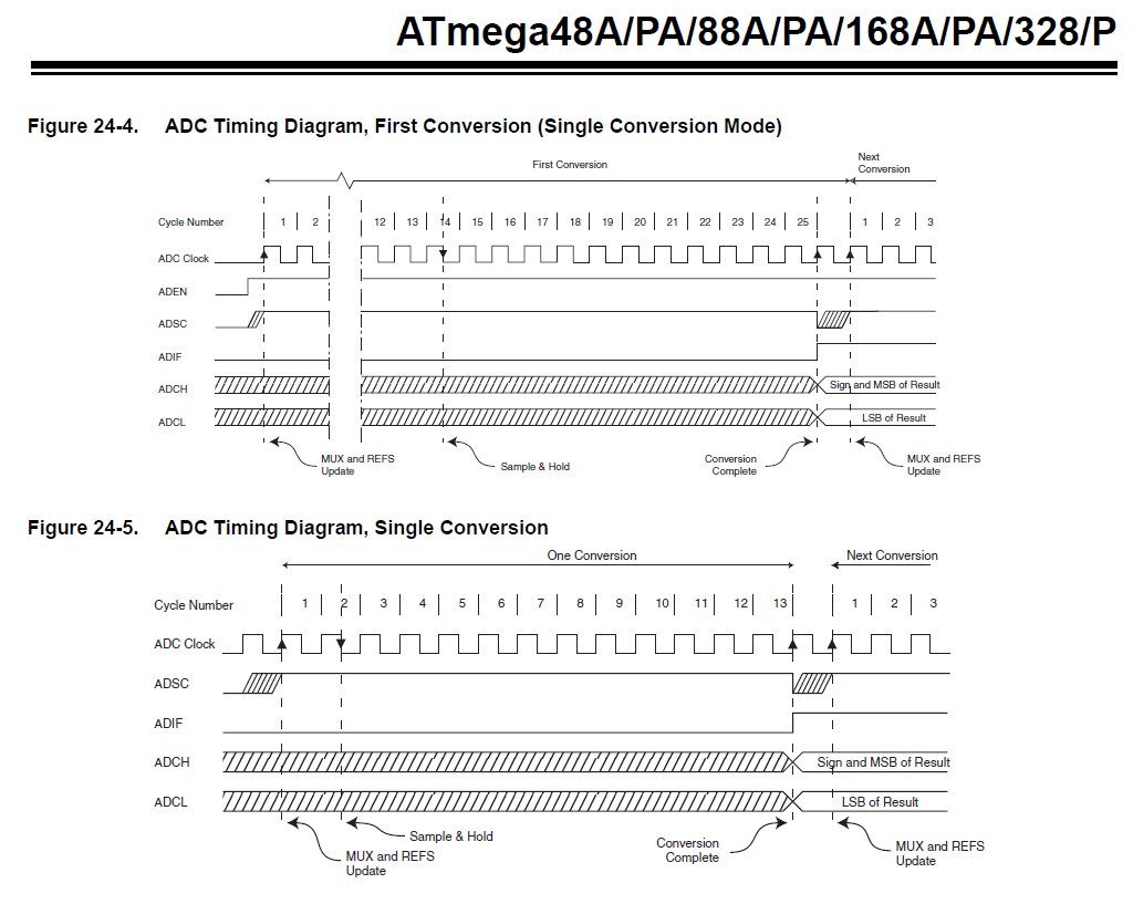
There might be some delay in the PORT peripherial, 1 clock cycle is to be expected, followed by a rise time that isn’t mentioned in the datasheet. I assume this comes to far less than 1 microsecond.
Within the ADC input circuitry some propagation delay is to be expected. In my test I tried to separate the gate time of the actual Sample/Hold circuit from anything else with the intent to test the limits of that S/H circuit. The results are surprising.

In this I made an assumption: the S/H gate really separates the S/H capacitor from the input selector. There is another solution: the chipmaker may have chosen to combine functions and uses the input selector as the gate switch for Sample/Hold. In this case things need to be interpreted differently to tally up to the timing diagrams: not the selected input is connected from ADSC to Hold, but the selected input is isolated from Hold to Conversion Complete. And now the change-over of the input selection is not the same as the start of the gate time anymore. I’m afraid this is a little confusing.
Next step in testing:

First visible signs of loss of resolution at ADC_clock 1MHz (DAC / comparator combo can’t keep up).
First visible signs of insufficient charging time at 2,75 microseconds (10xRC time, 14pF, internal R :: 20kOhm).
This test was run on a UNO R3, under favorable circumstances (room temperature, free airflow, supply from stable source (PC), signal sources with very low impedance)
Thanks for your results.
I agree. I also agree with you, that you should expect the digital output to settle at GND and + 5 V (actually about 10 mV from it) quite fast, and much faster than 1 us. One way to explain this is that there is some extra RC charging somewhere in the analog input circuit that remember the input signal from up to 2 us ago. Another way to explain the matter is, that the 14 pF S/H capacitor actually always is connected to the input (via some natural circuit resistance), and the only time that it is switched off, is while the ADC makes its conversion. I guess I like the last explanation best. I guess, that you should not change the input signal too fast after the 1.5 us period, while the S/H capacitor is being switched off the input. But there might be a way to test that as well.
In your next step testing, it seems like you measure from three different inputs in this sequence:
GND, GND, 3V3, 3V3, 5V, 5V, 3V3, 3V3, GND, 5V, GND - am I right?
I noticed, that you use the macro ADC, and I have seen it used by analogRead() as well. But do you know where to find the code for this macro?
In the forum I have seen some other ways in forum like this:
ADCvalue = ADCL | (ADCH << 8);
But with this other way I can't be sure, that ADCL is read before ADCH.
I got one question more, because I still learn C++. You got this line of code:
PINB |= 0b00100000; // toggle output PB5
it just seems to me, that bit 5 would remain high in PINB after first encounter of this line. But I can see from your result, that it do toggle.
Is this a possibility? :
PINB ^= 0b00100000;
I don’t use a macro. I directly address the registers of the peripherials. ADC is the name of a 16 bit register (alias ADCW). ADCL and ADCH are the names of the 8 bit registers that form the 16 bit register.
This is correct. The hardware requires the ADCL to be read first. But: the compiler knows this, myValue = ADC (or myValue = ADCW) will be translated into the right sequence of machine instructions. (Might be different for different microcontrollers.)
The EXOR is not useful here. This is a hardware trick within the peripherial. The PIN register is where you normally read the input values. You might expect writing to this register will have no effect. The chipmaker did add a function to this register: if a 1 is written to one of the bits, the corresponding bit in the PORT register (where you normally write the output values) is toggled. As the PIN register resides in the lower I/O space the compiler will translate the statement PINB |= 0b00100000 to 1 machine instruction. (Read the datasheet and the instruction set.)
https://ww1.microchip.com/downloads/aemDocuments/documents/MCU08/ProductDocuments/DataSheets/ATmega48A-PA-88A-PA-168A-PA-328-P-DS-DS40002061B.pdf
Thank you very much for your answer and help.
In wiring_analog.c I found a comment about an ADC macro, that I misunderstood. I have had a difficulty in finding how the names were defined for the compiler, but I think I found it in a strange folder structure with a file name called iom328p.h . It is likely short for input output memory. Other places you find definitions for the byte type addresses only, but not the 16 bit types. Timer1 got 16 bit registers as well.
Regarding the AVR instruction set. I can remember, that the old Pascal compilers, that I have worked with only used a subset of the internal registers of the CPU. Some code may use variables for short time use, and I wonder if it is possible to tell the C++ compiler to make use of "this" variable in an internal CPU register. The AVR of the 328P got 32 8 bit registers.
I have tried to measure the time consumption of each of these two statements:
ADCvalue = ADCL | (ADCH << 8);
and
ADCvalue = ADC;
It seems that the first is done in 4 clock cycles and the last in 8 clock cycles, and it is odd to me. I guess your reference to the instructions set might explain that.
Thanks for explaining this special function of the PIN registers. And this toggle function is clearly explained in section 14.2.2. When I read this datasheet, I did not go into detail with chapter 14 - it have a lot of detail.
The m comes from ATmega328. (There’s also avr/iotn167 for ATtiny167 and avr/iox16a4 for ATxmega16A4 etc.)
According to my disassembler reading ADC takes only 4 clock cycles. Did your measurement include storing the numbers to RAM?
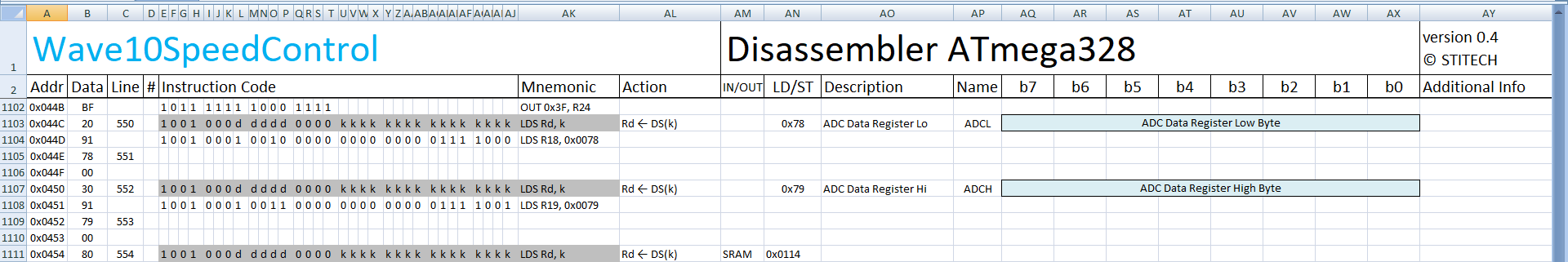
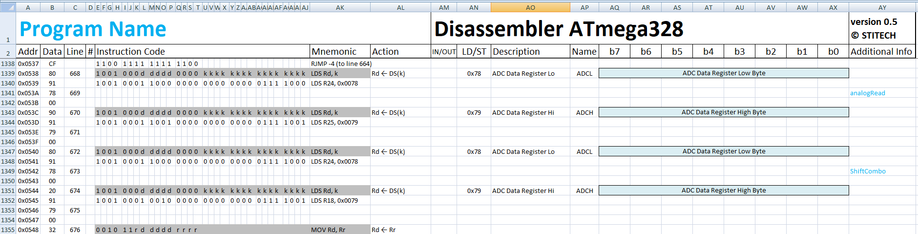
I wrote a miniprogram using ADCL | (ADCH << 8). Apparently the compiler recognizes 8 bit shifts as a full byte shift.
// analogRead_ShiftCombo
void setup() {
  Serial.begin(9600);
  uint16_t myValue = analogRead(A1);
  myValue = ADCL | (ADCH << 8);
  Serial.print(myValue);
}
void loop() {}
I also tried (ADCH << 8) | ADCL and that shows how easy it is to get it wrong.
I measured the duration via a hardware pin to oscilloscope of about 10 lines of same code. Then I added 50 lines of this code and measured how much the pulse on oscilloscope got longer. I guess, that the compiler consider these hardware ports as volatile data, because otherwise you cannot be sure if some compiler optimization will remove some of the code. But I am not 100% sure of this way of measuring. This is the code with 10 lines:
/*
This code is intended to test calculation speed of some aritmetric operations
and perhaps more. It may be done by using a testpin to be measured by oscilloscope

Result ADC read is (19.5 - 6.5us)/50 = 0.26 us - it is 4 clock cycles meaning 0.25 us.
  lowerADC = ADCL;                //ensures ADCL is read first lowerADC is of byte type
  ADCValue = (lowerADC | (ADCH << 8)); //reads ADC value

Result ADC read is the same as above, but it is a less secure way
  ADCValue = (ADCL | (ADCH << 8)); //reads ADC value

Result this ADC macro to read ADC value is (35 - 9us)/50 = 0.52 us - it is 8 clock cycles meaning 0.5 us.
ADCValue = ADC; //use of macro

It is likely, that an the basic timer interrupt for the Arduino core got 6.5 us execution time based
on what you can see as small more lenghy pulses from tests.
The old oscilloscope measures in general pulses about 4% longer, than they are.

Result a calculation (19.5 - 6.5us)/10 = 1.3 us. It is likely 1.25 us = 20 CPU clock cycles with CurrentControlP = 2
Result a calculation (21 - 6.5us)/10 = 1.45 us. It is likely 1.5 us = 24 CPU clock cycles with CurrentControlP = 4
Result a calculation (28 - 6.5us)/10 = 2.15 us. It is likely 34 CPU clock cycles with CurrentControlP = 8
Result a calculation (23 - 6.5us)/10 = 1.65 us. It is likely 26 CPU clock cycles with CurrentControlP = 7
Result a calculation (22.5 - 6.5us)/10 = 1.6 us. It is likely 26 CPU clock cycles with CurrentControlP = 3
Result a calculation (23 - 6.5us)/10 = 1.65 us. It is likely 26 CPU clock cycles with CurrentControlP = 31
Result a calculation (35 - 6.5us)/10 = 2.85 us. It is likely 46 CPU clock cycles with CurrentControlP = 32
Result a calculation (23 - 6.5us)/10 = 1.65 us. It is likely 26 CPU clock cycles with CurrentControlP = 48
outputValue = (((currentRef - currentValue) * CurrentControlP) >> 1) + Timer1TopDiv2; //duration calculation

Result a calculation (24.5 - 6.5us)/10 = 1.8 us. It is likely 29 CPU clock cycles with CurrentControlP = 48
outputValue = (((currentRef - currentValue) * CurrentControlP) >> 2) + Timer1TopDiv2; //duration calculation

Result of AnalogReadFast is 21 us, as they report themselves.

*/
#include "avdweb_AnalogReadFast.h"

const uint8_t TestOutPin = PD6;         // Test pin for signal to oscilloscope
const uint8_t AnalogPotPin = A0;        // Analog input pin that the potentiometer is attached to

const int Timer1TopDiv2 = 400;
const byte CurrentControlP = 48;
const unsigned long int PrintPeriodMs = 3000;

byte lowerADC = 0;
byte testValue = 0;
unsigned long int printTrigMillis = 0;
int ADCValue = 0;
volatile int outputValue = 0;
volatile int currentRef = 355;
volatile int currentValue = 345;

void setup() {
  Serial.begin(9600);
  pinMode(TestOutPin, OUTPUT);
  digitalWrite(TestOutPin,LOW);
  pinMode(AnalogPotPin, INPUT);
  printTrigMillis = millis() + PrintPeriodMs;
  //lowerADC = ADC_CTRLB_PRESCALER_DIV64;

}

void loop() {
  // put your main code here, to run repeatedly:
  digitalWrite(TestOutPin,HIGH);
  ADCValue = analogRead(A0);
  ADCValue = ADC;
  ADCValue = ADC;
  ADCValue = ADC;
  ADCValue = ADC;
  ADCValue = ADC;
  ADCValue = ADC;
  ADCValue = ADC;
  ADCValue = ADC;
  ADCValue = ADC;
  ADCValue = ADC;
  //10 times

  digitalWrite(TestOutPin,LOW);
  delay(1);
  if (millis() > printTrigMillis) {
    printTrigMillis += PrintPeriodMs;
    // print the results to the Serial Monitor:
    //Serial.print("potValue = "); Serial.print(potValue);

    Serial.print("\t ADCValue = "); Serial.print(ADCValue);
    Serial.print("\t testValue = "); Serial.print(testValue,BIN);

    Serial.println();
    };
}
I don’t really understand that program. What I do see is: 10 times reading ADC, a digitalWrite() and an analogRead().
In my disassembler I can see that reading ADC takes 4 clock cycles, plain and simple, thus 10 times takes 2.5 microseconds.
The disassembled digitalWrite() contains several branches, so counting machine instructions won’t work. I once timed it using one of the timer/counters and measured 3.68 microseconds. Compare this to the 2.5 microseconds of the ADC readings.
The same goes for the analogRead(). I measured that at 112 microseconds. Compare that to the 2.5 microseconds of the ADC readings. In short: the inaccuracies of your oscilloscope method are bigger than what you try to measure.
By the way, I saw a reference to analogReadFast(). Beware of this trick! It does go faster, 8 times faster to be precise. But that means the DAC/comparator combo may not be able to keep up with the clock speed and you may lose a bit, and not necessarily the Least Significant Bit. Aside from that there is the time to charge the Sample/Hold capacitor that is 8 times shorter now.
If you’re still trying to charge batteries, mind that accuracy is important. The difference between 4.2V and 4.4V on a Li-ion is a house burning down.
I am sorry about this. I just measured this again, and can confirm the 4 clock cycles by oscilloscope. I shall try to explain the method better, my code above was actually wrong.
I first measure the pulse width on the hardware pin with this code. It was 6.5 us:
/*
This code is intended to test calculation speed of some aritmetric operations
and perhaps more. It may be done by using a testpin to be measured by oscilloscope

Result ADC read is (19.5 - 6.5us)/50 = 0.26 us - it is 4 clock cycles meaning 0.25 us.
  lowerADC = ADCL;                //ensures ADCL is read first lowerADC is of byte type
  ADCValue = (lowerADC | (ADCH << 8)); //reads ADC value

Result ADC read is the same as above, but it is a less secure way
  ADCValue = (ADCL | (ADCH << 8)); //reads ADC value

Result reading ADC from 10 times to 60 times value is (19 - 6.5us)/50 = 0.25 us - it is 4 clock cycles meaning 0.25 us.
ADCValue = ADC; //

It is likely, that an the basic timer interrupt for the Arduino core got 6.5 us execution time based
on what you can see as small more lenghy pulses from tests.
The old oscilloscope measures in general pulses about 4% longer, than they are.

Result a calculation (19.5 - 6.5us)/10 = 1.3 us. It is likely 1.25 us = 20 CPU clock cycles with CurrentControlP = 2
Result a calculation (21 - 6.5us)/10 = 1.45 us. It is likely 1.5 us = 24 CPU clock cycles with CurrentControlP = 4
Result a calculation (28 - 6.5us)/10 = 2.15 us. It is likely 34 CPU clock cycles with CurrentControlP = 8
Result a calculation (23 - 6.5us)/10 = 1.65 us. It is likely 26 CPU clock cycles with CurrentControlP = 7
Result a calculation (22.5 - 6.5us)/10 = 1.6 us. It is likely 26 CPU clock cycles with CurrentControlP = 3
Result a calculation (23 - 6.5us)/10 = 1.65 us. It is likely 26 CPU clock cycles with CurrentControlP = 31
Result a calculation (35 - 6.5us)/10 = 2.85 us. It is likely 46 CPU clock cycles with CurrentControlP = 32
Result a calculation (23 - 6.5us)/10 = 1.65 us. It is likely 26 CPU clock cycles with CurrentControlP = 48
outputValue = (((currentRef - currentValue) * CurrentControlP) >> 1) + Timer1TopDiv2; //duration calculation

Result a calculation (24.5 - 6.5us)/10 = 1.8 us. It is likely 29 CPU clock cycles with CurrentControlP = 48
outputValue = (((currentRef - currentValue) * CurrentControlP) >> 2) + Timer1TopDiv2; //duration calculation

Result of AnalogReadFast is 21 us, as they report themselves.

*/
#include "avdweb_AnalogReadFast.h"

const uint8_t TestOutPin = PD6;         // Test pin for signal to oscilloscope
const uint8_t AnalogPotPin = A0;        // Analog input pin that the potentiometer is attached to

const int Timer1TopDiv2 = 400;
const byte CurrentControlP = 48;
const unsigned long int PrintPeriodMs = 3000;

byte lowerADC = 0;
byte testValue = 0;
unsigned long int printTrigMillis = 0;
int ADCValue = 0;
volatile int outputValue = 0;
volatile int currentRef = 355;
volatile int currentValue = 345;

void setup() {
  Serial.begin(9600);
  pinMode(TestOutPin, OUTPUT);
  digitalWrite(TestOutPin,LOW);
  pinMode(AnalogPotPin, INPUT);
  printTrigMillis = millis() + PrintPeriodMs;
  //lowerADC = ADC_CTRLB_PRESCALER_DIV64;

}

void loop() {
  // put your main code here, to run repeatedly:
  ADCValue = analogRead(A0);
  digitalWrite(TestOutPin,HIGH);
  ADCValue = ADC;
  ADCValue = ADC;
  ADCValue = ADC;
  ADCValue = ADC;
  ADCValue = ADC;
  ADCValue = ADC;
  ADCValue = ADC;
  ADCValue = ADC;
  ADCValue = ADC;
  ADCValue = ADC;
  //10 times

  digitalWrite(TestOutPin,LOW);
  delay(1);
  if (millis() > printTrigMillis) {
    printTrigMillis += PrintPeriodMs;
    // print the results to the Serial Monitor:
    //Serial.print("potValue = "); Serial.print(potValue);

    //Serial.print("\t ADCValue = "); Serial.print(ADCValue);
    //Serial.print("\t testValue = "); Serial.print(testValue,BIN);

    //Serial.println();
    };
}
Then I measure the pulse width with this code (with 50 extra lines of code). It was 19 us:
/*
This code is intended to test calculation speed of some aritmetric operations
and perhaps more. It may be done by using a testpin to be measured by oscilloscope

Result ADC read is (19.5 - 6.5us)/50 = 0.26 us - it is 4 clock cycles meaning 0.25 us.
  lowerADC = ADCL;                //ensures ADCL is read first lowerADC is of byte type
  ADCValue = (lowerADC | (ADCH << 8)); //reads ADC value

Result ADC read is the same as above, but it is a less secure way
  ADCValue = (ADCL | (ADCH << 8)); //reads ADC value

Result reading ADC from 10 times to 60 times value is (19 - 6.5us)/50 = 0.25 us - it is 4 clock cycles meaning 0.25 us.
ADCValue = ADC; //

It is likely, that an the basic timer interrupt for the Arduino core got 6.5 us execution time based
on what you can see as small more lenghy pulses from tests.
The old oscilloscope measures in general pulses about 4% longer, than they are.

Result a calculation (19.5 - 6.5us)/10 = 1.3 us. It is likely 1.25 us = 20 CPU clock cycles with CurrentControlP = 2
Result a calculation (21 - 6.5us)/10 = 1.45 us. It is likely 1.5 us = 24 CPU clock cycles with CurrentControlP = 4
Result a calculation (28 - 6.5us)/10 = 2.15 us. It is likely 34 CPU clock cycles with CurrentControlP = 8
Result a calculation (23 - 6.5us)/10 = 1.65 us. It is likely 26 CPU clock cycles with CurrentControlP = 7
Result a calculation (22.5 - 6.5us)/10 = 1.6 us. It is likely 26 CPU clock cycles with CurrentControlP = 3
Result a calculation (23 - 6.5us)/10 = 1.65 us. It is likely 26 CPU clock cycles with CurrentControlP = 31
Result a calculation (35 - 6.5us)/10 = 2.85 us. It is likely 46 CPU clock cycles with CurrentControlP = 32
Result a calculation (23 - 6.5us)/10 = 1.65 us. It is likely 26 CPU clock cycles with CurrentControlP = 48
outputValue = (((currentRef - currentValue) * CurrentControlP) >> 1) + Timer1TopDiv2; //duration calculation

Result a calculation (24.5 - 6.5us)/10 = 1.8 us. It is likely 29 CPU clock cycles with CurrentControlP = 48
outputValue = (((currentRef - currentValue) * CurrentControlP) >> 2) + Timer1TopDiv2; //duration calculation

Result of AnalogReadFast is 21 us, as they report themselves.

*/
#include "avdweb_AnalogReadFast.h"

const uint8_t TestOutPin = PD6;         // Test pin for signal to oscilloscope
const uint8_t AnalogPotPin = A0;        // Analog input pin that the potentiometer is attached to

const int Timer1TopDiv2 = 400;
const byte CurrentControlP = 48;
const unsigned long int PrintPeriodMs = 3000;

byte lowerADC = 0;
byte testValue = 0;
unsigned long int printTrigMillis = 0;
int ADCValue = 0;
volatile int outputValue = 0;
volatile int currentRef = 355;
volatile int currentValue = 345;

void setup() {
  Serial.begin(9600);
  pinMode(TestOutPin, OUTPUT);
  digitalWrite(TestOutPin,LOW);
  pinMode(AnalogPotPin, INPUT);
  printTrigMillis = millis() + PrintPeriodMs;
  //lowerADC = ADC_CTRLB_PRESCALER_DIV64;

}

void loop() {
  // put your main code here, to run repeatedly:
  ADCValue = analogRead(A0);
  digitalWrite(TestOutPin,HIGH);
  ADCValue = ADC;
  ADCValue = ADC;
  ADCValue = ADC;
  ADCValue = ADC;
  ADCValue = ADC;
  ADCValue = ADC;
  ADCValue = ADC;
  ADCValue = ADC;
  ADCValue = ADC;
  ADCValue = ADC;
  //10 times
  ADCValue = ADC;
  ADCValue = ADC;
  ADCValue = ADC;
  ADCValue = ADC;
  ADCValue = ADC;
  ADCValue = ADC;
  ADCValue = ADC;
  ADCValue = ADC;
  ADCValue = ADC;
  ADCValue = ADC;
  //10 times
  ADCValue = ADC;
  ADCValue = ADC;
  ADCValue = ADC;
  ADCValue = ADC;
  ADCValue = ADC;
  ADCValue = ADC;
  ADCValue = ADC;
  ADCValue = ADC;
  ADCValue = ADC;
  ADCValue = ADC;
  //10 times
  ADCValue = ADC;
  ADCValue = ADC;
  ADCValue = ADC;
  ADCValue = ADC;
  ADCValue = ADC;
  ADCValue = ADC;
  ADCValue = ADC;
  ADCValue = ADC;
  ADCValue = ADC;
  ADCValue = ADC;
  //10 times
  ADCValue = ADC;
  ADCValue = ADC;
  ADCValue = ADC;
  ADCValue = ADC;
  ADCValue = ADC;
  ADCValue = ADC;
  ADCValue = ADC;
  ADCValue = ADC;
  ADCValue = ADC;
  ADCValue = ADC;
  //10 times
  ADCValue = ADC;
  ADCValue = ADC;
  ADCValue = ADC;
  ADCValue = ADC;
  ADCValue = ADC;
  ADCValue = ADC;
  ADCValue = ADC;
  ADCValue = ADC;
  ADCValue = ADC;
  ADCValue = ADC;
  //10 times - 60 in all

  digitalWrite(TestOutPin,LOW);
  delay(1);
  if (millis() > printTrigMillis) {
    printTrigMillis += PrintPeriodMs;
    // print the results to the Serial Monitor:
    //Serial.print("potValue = "); Serial.print(potValue);

    //Serial.print("\t ADCValue = "); Serial.print(ADCValue);
    //Serial.print("\t testValue = "); Serial.print(testValue,BIN);

    //Serial.println();
    };
}
So the 50 extra lines of code caused an increase from 6.5 us to 19 us and it is 12.5 us. It was 50 times, so it is 0.25 us each line, and it is equal to 4 clock cycles. ![]()
In the test I made on my Arduino Nano in the start of this thread (with no mux change). I could only see a small increase in errors of about ½ LSB from going from 125 kHz to 1 MHz ADC clock. 2 MHz cause a significant change to the worse. But it could be different on other batches produced of this chip.
However, the S/H charging and its connection to the analog multiplexer becomes a much more significant issue at 1 MHz, and it should be taken care of, if you want to use 1 MHz.