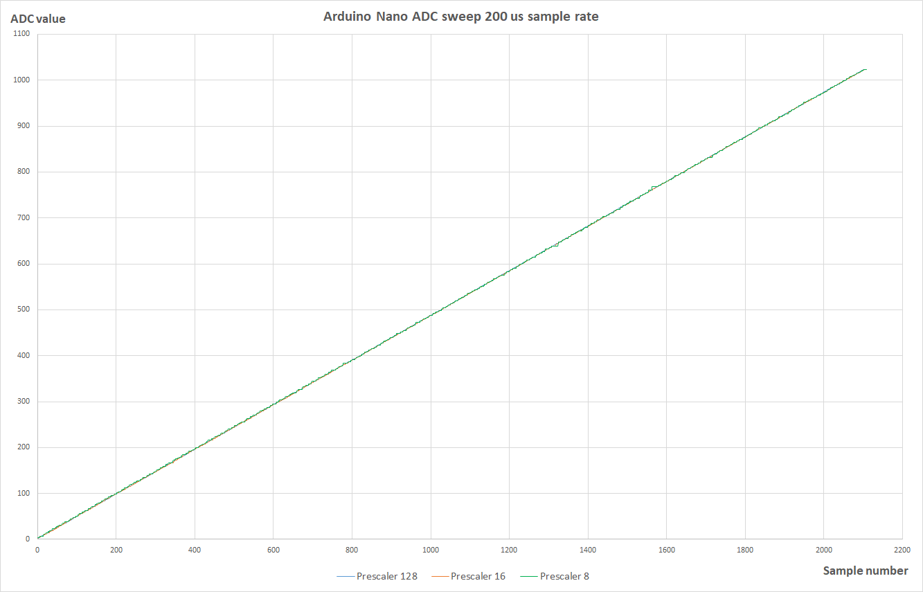
I made a test of my Arduino Nano PCB to evaluate how a change of the ADC prescaler influence the quantization error of the ADC. A prescaler value of 128, 16, and 8 was tested, which provide an ADC clock of 125 kHz, 1 MHz, and 2 MHz.
I made a program to control a sweep generator made by a rail to rail op-amp implementing an integrator as you see here:
I can upload the program code, if you think it is relevant.
It samples 750 values with a sample rate of 5 kHz. Three sweeps of each prescaler valule was done to get 3x750 samples for a hole sweep. It makes 9 single runs in all to obtain the curves below. In this way you will ideally get at least two samples with the same ADC-value in the sweep.
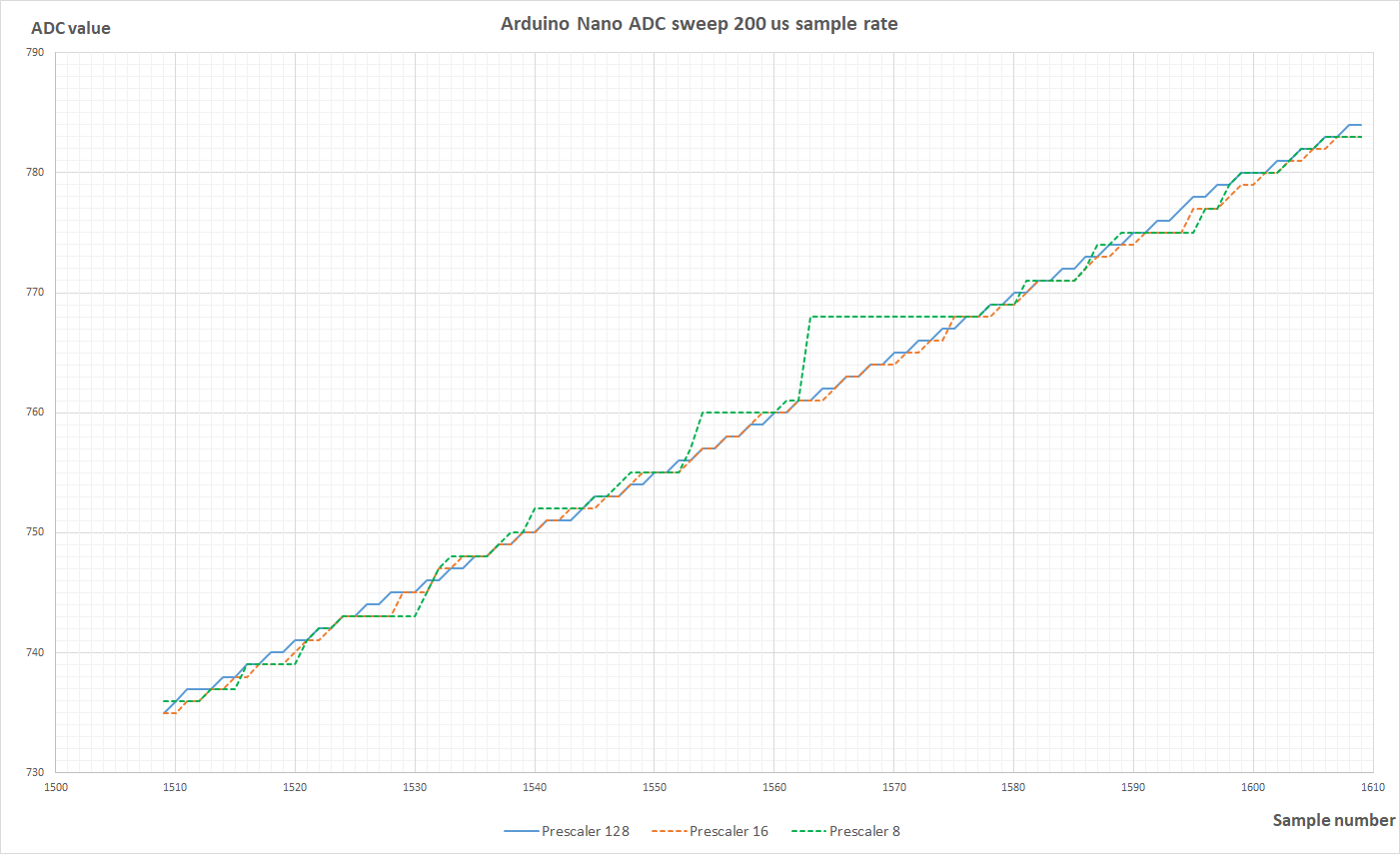
The curve below is the same data, when you zoom in some data. With the fast ADC clock, you have some ADC values, that the ADC "prefer" to deliver. Then it becomes unlikely that the ADC provide some neighbor values. It is easy to see with the prescaler at 8, but at prescaler at 16, you see a small tendency of the same problem.
I have previously seen recommendations, that you should be able to use a prescaler value of 16 with the classical Arduino without too much error, and I think this test confirms that statement. I have not seen test data, that could confirm what was going on. So I hope this data can help you.
If you have seen other test data of the ADC converter and other ways to test it, I should like to know about that.
You will of cause not find an exact repetition. I think I zoomed at one of the worst cases in order to provide some understanding of the behavior. There is of cause also a bit of normal noise here.
Is it possible to upload the Excel-sheet here? Then you can investigate the data yourselves.
I was just thinking about random noise. Can You make a little drawing for the analog parts and take a picture of the fysical setup?
What other electriacl installations are there nere/around You? Know that the ramp generator also is a suspect.....
As far as I can evaluate this, it is not ordinary noise, that is the main problem with higher ADC clock. It is the quantization error. One way for me to confirm this would be, to repeat the sweep with the prescaler at 8 some times and zoom at the same part of the curve. Then you should see the same kind of quantization errors occur again. In this way you can rule out normal noise. What do you think about that?
Are there some parts of these data, that you find hard to believe as being true?
Not likely. It's to much. One uncertainty is the mains supplying the 5 volt converter. The long leads to/from the resistors. That setup is not suitable for low noise, precision measurments as I see it.
In the datasheet for the microcontroller chip, ATmega328/P you find this statement:
"By default, the successive approximation circuitry requires an input clock frequency between 50kHz and 200kHz to get maximum resolution. If a lower resolution than 10 bits is needed, the input clock frequency to the ADC can be higher than 200kHz to get a higher sample rate."
The default ADC clock frequency used with the Arduino Nano is 125 kHz. Above I show data for the ADC clock at 1 MHz and 2 MHz as well. It is a frequency significantly above, what the chip manufacturer recommend. The question here is how much degradation of ADC performance you get and what kind of degradation, you get, when you use the Arduino this way.
I agree, that the physical lay-out is not optimized for low noise. I do think, that the values given by the ADC at 125 kHz seem quite stable and without much noise. If the circuit had problems, you would see more noise in this case. Therefore I think, that the circuit is sufficient to prove, that quantization error starts to kick in at the higher ADC clocks.
Does the specification tell what type of AD converter it is, how it works? There is a successive approximation way to do it, and other ways. Some AD converters charge a capacitor during a short time and then do the conversion from the capacitor voltage. Clocking at excessive rates obviously must lead to difficulties. However this doesn't explain the irregularity You showed. Repeating the test and comparing the outcome ought to be interesting.
Yes, it is a successive approximation AD converter, that is used in the 328P chip.
Yes, they are named Dual-slope AD-converters. It is a slow, but accurate AD-converter. It will normally not make use of a sample-hold circuit, and it averages the signal measured over the longer time it uses for conversion. It is hardly used anymore with microcontrollers, but it was quite common to use it 40 years ago.
I am not that familiar with AD-converters, but I guess that the behavior I show would be normal for a successive approximation AD-converter, when you start to clock it faster than specified. You have got a critical comparator in the circuit, and it have a hard time to settle in time when some of the more significant bits change. You see that the value stuck at 768, and it is binary 1100000000. So just after the second most important bit had changed, it seems to influence the stability for the lower bits.
I just measured the values three times with the 2 MHz ADC clock, and you see the result here:
I think you find the same behavior in all three sweeps.
I like to have some faster conversation in an application of some accurate low speed control of an DC motor. The tests confirms for me, that an ADC clock of 1 MHz should be OK for me to use, but 2 MHz starts to show too high errors.
But I think that the behavior of the ADC of this popular microcontroller may have some broader interest among users, and that is why I present the data here. Perhaps some other forum user could add some other significant information about the same subject. I guess this is what a forum can be used for, and not only questions and answers regarding actual problems.
Regarding electromagnetic compatibility, I am an expert, and I have advised and educated many electronical engineers on that subject for many years professionally. Stray noise is not the issue here. You cannot repeat the same measurements like I just presented, if the errors was due to stray noise. I have to say, you are wrong.
Electrical noise can be a difficult problem, but it is not the case here. You have to prove me wrong by showing data, that an ADC in a 328P clocked at 2 MHz perform significantly better, than I show here. Have you seen such data before?
So, the lesson learned here is that if you attempt to use the ADC far outside of the manufacturer's recommended operating conditions, it doesn't work well.
Quantization error for a given ADC is fixed, it is not dependent on sample rate.
Not sure what your measurements show but it is not related to quantization error.
The best way to use circuits is to read the max, min specifications and stay within the limits. Stepping above max might work for one individual but not another.
You can say that. But I like to know how much degradation, that could be expected when you increasing ADC clock. The issue have been addressed several times when you search this forum, but I have not seen measurement data, and then it becomes a bit hard to evaluate. This is one of the better threads in the past: https://forum.arduino.cc/t/fast-sampling-adc/64877
The good thing the data show is, that the ADC works quite well under normal conditions up to an eight time higher conversion frequency with a ADC clock of 1 MHz. I would think that you lost about ½ to 1 bit in accuracy. At 2 MHz, you get at significant decrease, and at some conversion values you lost 3 bit in accuracy. I think this is significant information for a user, that wants shorter ADC conversion time.
I tried to upload the Excel-file, like you upload a picture-file in this forum. The uploader informs me, that I am only allowed to upload specific types of files, that is mostly picture files. I think it is because excel files can contain malware, and a serious forum administrator would not allow that to happen.
In my first post a sketch of the analog integrator with its two connections to the Arduino is shown. Of cause the power supply of about 5 VDC is also connected.
I use the USB connection to the PC to provide power. But I did also try another 5 VDC. The ADC do also work with this supply voltage for reference. When you start to analyze this, a change in DC voltage should not change the results. With a 4.5 VDC voltage you get the same time for the integrator to sweep from 0 V to 4.5 VDC, and therefore the sampled ADC values are the same. Supply ripple voltage can cause decreased accuracy, but it will show a different pattern in the result.
ADC clock is not used to control sample rate. ADC clock is used internally by the ADC for the successive conversion process. According to datasheet the full process of sample hold and conversion takes 13½ clock cycles.
The sample rate is controlled by the software, and I start a conversion each 200 us (5 kHz) based on a busy-wait reading the micros() function. So the sample rate was the same for all the tests I did.
The quantization error is the difference between the provided ADC value (converted to voltage) and the exact analog voltage that the ADC measures without noise. When you start to increase the ADC clock, you introduce increased quantization error above the normal rounding that an ADC do. Do you have a better name for this error? https://www.sciencedirect.com/topics/engineering/quantization-error
Unfortunately your data only applies to your particular 328P. Since you are running tests outside of the recommended operating parameters, there is no reason to assume that your data applies to all 328Ps manufactured. For your data to have any statistical significance you would have to run your tests on at least 100 different parts.
Quantization error for a given ADC is fixed, it is not dependent on sample rate or clock frequency.
The errors you are seeing are of an unknown origin, however, quantization will be part of the error but it is not the total reason for the errors you see.
The are many thing that contribute to ADC errors:
Gain error
Offset error.
Integral Non-linearity
Differential Non-linearity
The error you are measuring is sometimes called Total absolute error or Absolute accuracy or Total Unadjusted Error (TUE), basically it includes all errors including quantization error.
Yes, I agree. For any professional use of this chip, you should not go outside the manufacturers recommendations. The datasheet allows a faster clock, and just says that the accuracy decrease, but not how much. Just as an example - what happen if you use the Arduino at temperatures of 0 C or 50 C. But for amateurs anything is allowed, and I guess most users here are amateurs.
However, I am not the first one reporting some information on this issue. In the link I provided above you see this curve:
I cannot recommend to use this curve unless you know the preconditions, and I do not.
When you search by Google, you will find a lot of information about this, but nothing serious with data. But I think I found quite many stating, that the degradation, when you use 1 MHz clock is not that serious.