I soldered R5.
I send to nano that;
#include <Arduino.h>
#include <U8g2lib.h>
#include <SPI.h>
#include <Wire.h>
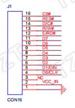
//U8G2_SSD1322_NHD_256X64_1_4W_SW_SPI u8g2(U8G2_R0, /* clock=*/ 13, /* data=*/ 11, /* cs=*/ 10, /* dc=*/ 9, /* reset=*/ 8);	// Enable U8G2_16BIT in u8g2.h
U8G2_SSD1322_NHD_256X64_1_4W_HW_SPI u8g2(U8G2_R0, /* cs=*/ 10, /* dc=*/ 9, /* reset=*/ 8);	// Enable U8G2_16BIT in u8g2.h
void setup(void) {
u8g2.begin();
}
void loop(void) {
u8g2.firstPage();
do {
u8g2.setFont(u8g2_font_ncenB14_tr);
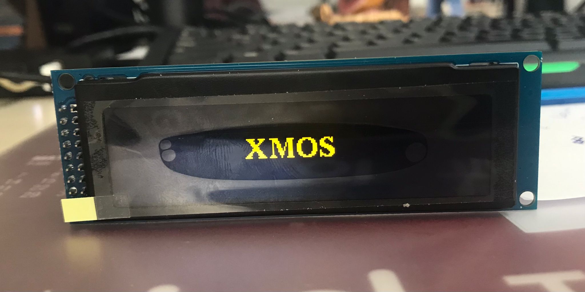
u8g2.drawStr(0,24,"Hello World!");
} while ( u8g2.nextPage() );
}
But lots of error;
Arduino:1.8.19 (Windows 10), Kart:"Arduino Nano, ATmega328P"
Çalışmanız programın 9508 bayt (30 %) saklama alanını kullandı. Maksimum 30720 bayt.
Global değişkenler belleğin 748 byte kadarını (36%) kullanıyor. Yerel değişkenler için 1300 byte yer kalıyor. En fazla 2048 byte kullanılabilir.
avrdude: stk500_recv(): programmer is not responding
avrdude: stk500_getsync() attempt 1 of 10: not in sync: resp=0xea
avrdude: stk500_recv(): programmer is not responding
avrdude: stk500_getsync() attempt 2 of 10: not in sync: resp=0xea
avrdude: stk500_recv(): programmer is not responding
avrdude: stk500_getsync() attempt 3 of 10: not in sync: resp=0xea
avrdude: stk500_recv(): programmer is not responding
avrdude: stk500_getsync() attempt 4 of 10: not in sync: resp=0xea
avrdude: stk500_recv(): programmer is not responding
avrdude: stk500_getsync() attempt 5 of 10: not in sync: resp=0xea
avrdude: stk500_recv(): programmer is not responding
avrdude: stk500_getsync() attempt 6 of 10: not in sync: resp=0xea
Problem uploading to board. See https://support.arduino.cc/hc/en-us/sections/360003198300 for suggestions.
avrdude: stk500_recv(): programmer is not responding
avrdude: stk500_getsync() attempt 7 of 10: not in sync: resp=0xea
avrdude: stk500_recv(): programmer is not responding
avrdude: stk500_getsync() attempt 8 of 10: not in sync: resp=0xea
avrdude: stk500_recv(): programmer is not responding
avrdude: stk500_getsync() attempt 9 of 10: not in sync: resp=0xea
avrdude: stk500_recv(): programmer is not responding
avrdude: stk500_getsync() attempt 10 of 10: not in sync: resp=0xea
SW_SPI and HW_SPI are same results.