Hi Guys,
I am beginner to arduino. Please help with my query guys
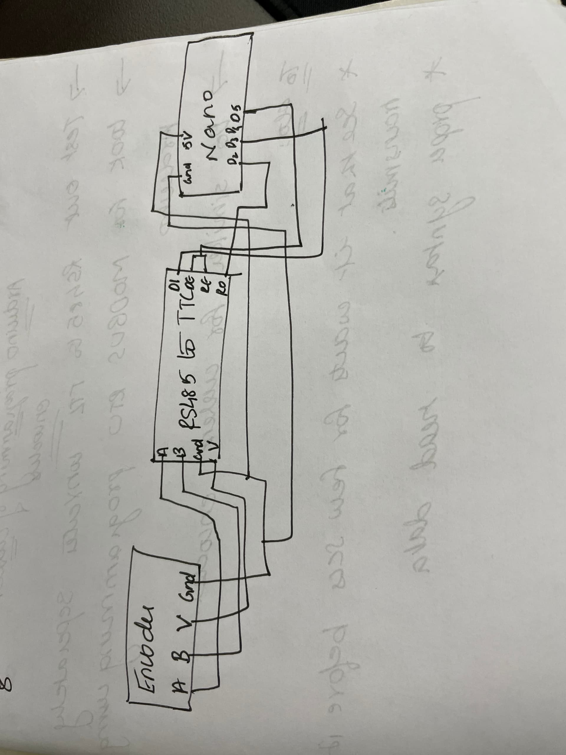
I have a encoder with a RS485 interface. the encoder communicates over MODBUS RTU interface.
I am connecting the encoder to the Arduino nano using a RS485-TTL MAX485 Converter.
Can someone Pls help with the arduino code and connections to get the values from the encoder in the serial monitor of the arduino.
Below are my encoder register details
Questions about MODBUS are quite common. Try the Search Forum function in this window, up to the right. Use "Arduino + MODBUS". You can do the same for "Arduino + Encoder".
#include <ModbusMaster.h>
#include <SoftwareSerial.h>

// Modbus configuration
#define MODBUS_DIR_PIN       5   // Connect DE, RE pins of MAX485
#define MODBUS_RX_PIN        2  // Rx pin for SoftwareSerial
#define MODBUS_TX_PIN        3  // Tx pin for SoftwareSerial
#define MODBUS_SERIAL_BAUD   9600 // Baud rate for Modbus RTU communication

// Encoder register address
uint16_t encoderRegister = 0x0000;

// Encoder resolution
const uint32_t ENCODER_RESOLUTION = 1024; // 10-bit resolution (1024 P/R)

// Initialize the ModbusMaster object
ModbusMaster node;

// SoftwareSerial for Modbus communication
SoftwareSerial modbusSerial(MODBUS_RX_PIN, MODBUS_TX_PIN);

// Pin 5 made high for Modbus transmission mode
void modbusPreTransmission()
{
  delay(500);
  digitalWrite(MODBUS_DIR_PIN, HIGH);

}

// Pin 5 made low for Modbus receive mode
void modbusPostTransmission()
{
  digitalWrite(MODBUS_DIR_PIN, LOW);
 delay(500);
}

void setup() {
  // Initialize the built-in hardware serial communication
  Serial.begin(9600);  // Default settings: 9600bps, 8 data bits, no parity, 1 stop bit
  while (!Serial) {
    ; // Wait for serial port to connect (needed for native USB port only)
  }

  // Initialize SoftwareSerial for Modbus communication
  modbusSerial.begin(MODBUS_SERIAL_BAUD);

  // Set up the Modbus direction pin
  pinMode(MODBUS_DIR_PIN, OUTPUT);
  digitalWrite(MODBUS_DIR_PIN, LOW);

  // Initialize ModbusMaster with the slave ID and software serial port
  node.begin(1, modbusSerial);  // Default station number is 1

  // Set pre and post transmission callbacks for RS485 transceiver configuration
  node.preTransmission(modbusPreTransmission);
  node.postTransmission(modbusPostTransmission);
}

void loop() {
  uint8_t result;
  uint16_t data[2];

  // Read encoder value from Modbus register 0x0000 using function code 0x03
  result = node.readHoldingRegisters(encoderRegister, 2);

  if (result == node.ku8MBSuccess) {
    Serial.println("Success, Received data: ");

    // Retrieve the 32-bit data from the response buffer
    data[0] = node.getResponseBuffer(0x00);
    data[1] = node.getResponseBuffer(0x01);

    // Combine the two 16-bit values into a 32-bit value
    uint32_t encoderValue = ((uint32_t)data[0] << 16) | data[1];

    // Map the 32-bit encoder value to the 10-bit resolution
    uint16_t mappedValue = encoderValue % ENCODER_RESOLUTION;

    // Print the mapped encoder value
    Serial.print("Mapped Encoder Value: ");
    Serial.println(mappedValue);
  } else {
    Serial.print("Failed, Response Code: ");
    Serial.print(result, HEX);
    Serial.println("");
    delay(5000);
  }

  // Add a delay before the next iteration
  delay(1000);
}
i get the error 11:50:43.891 -> Failed, Response Code: E2
Any ideas on how to rectify thisUse code tags to format code for the forum
I am getting the vales now. but there are squares in my output. following is my code and results. how to elimiate these squares
`#include <ModbusMaster.h>

// Modbus configuration
#define MODBUS_DIR_PIN       5   // Connect DE, RE pins of MAX485
#define MODBUS_SERIAL_BAUD   115200 // Keep the baud rate as 115200

// Encoder register address
uint16_t encoderRegister = 0x0000;

// Initialize the ModbusMaster object
ModbusMaster node;

// Pin 4 made high for Modbus transmission mode
void modbusPreTransmission()
{
  digitalWrite(MODBUS_DIR_PIN, HIGH);
  delayMicroseconds(10);  // Adjust the delay if needed
}

// Pin 4 made low for Modbus receive mode
void modbusPostTransmission()
{
  digitalWrite(MODBUS_DIR_PIN, LOW);
  delayMicroseconds(10);  // Adjust the delay if needed
}

void setup() {
  // Initialize the built-in hardware serial communication
  Serial.begin(MODBUS_SERIAL_BAUD);

  // Set up the Modbus direction pin
  pinMode(MODBUS_DIR_PIN, OUTPUT);
  digitalWrite(MODBUS_DIR_PIN, LOW);

  // Initialize ModbusMaster with the slave ID and hardware serial port
  node.begin(1, Serial);  // Using hardware serial

  // Set pre and post transmission callbacks for RS485 transceiver configuration
  node.preTransmission(modbusPreTransmission);
  node.postTransmission(modbusPostTransmission);
}

void loop() {
  uint8_t result;
  uint16_t data;
  unsigned long startTime, endTime;

  // Record the start time before sending the request
  startTime = micros();  // Use micros() for more accurate timing

  // Read encoder value from Modbus register 0x0000 using function code 0x03
  result = node.readHoldingRegisters(encoderRegister, 1);

  // Record the end time after receiving the response
  endTime = micros();  // Use micros() for more accurate timing

  if (result == node.ku8MBSuccess) {
    Serial.println("Success, Received data: ");

    // Retrieve the 16-bit data from the response buffer
    data = node.getResponseBuffer(0x00);

    // Print the received value
    Serial.print("Received Value: ");
    Serial.println(data);

    // Print the time taken for the response
    Serial.print("Time taken: ");
    Serial.print(endTime - startTime);
    Serial.println(" microseconds");
  } else {
    Serial.print("Failed, Response Code: ");
    Serial.print(result, HEX);
    Serial.println("");
  }

  // Add a delay before the next iteration if necessary
  delay(1000);
}