Hello everyone, i'm having a problem.
well i have an arduino nano, this nano is wired with a relay board 8 channel, power source for the relay board is 5v 2 amps, the power source for arduino is sepearted from the relay board, in this case nothing happen, everything works fine and no probleme occured.
After i added 220v ac solenoid valves to the relay board, the valves light up normally, when they close, the arduino reset it self, until i disconnect power source and conenct it again so the program start again,
what should i do please !!
the relay board is like this one : https://www.amazon.com/SainSmart-8-CH-8-Channel-Relay-Module/dp/B0057OC5WK
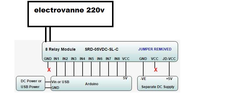
my circuit is like this : "see attachements"
It looks like you're missing a GND connection between the relay board and the Arduino.
pylon:
It looks like you're missing a GND connection between the relay board and the Arduino.
You don't need that. Arduino Vcc 5V through optocoupler on relay board through Arduino pin to GND
You don't need that.
Interesting. And where does the relay board gets the reference from for all the pins the Arduino connects to it? Even if you use optocouplers on the relay board the optocoupler must know what reference the Arduino signals are based on.
pylon:
Interesting. And where does the relay board gets the reference from for all the pins the Arduino connects to it?
In this case, it's from the Arduino +5V.
pylon:
Interesting. And where does the relay board gets the reference from for all the pins the Arduino connects to it? Even if you use optocouplers on the relay board the optocoupler must know what reference the Arduino signals are based on.
I can't explain better without making a drawing, but compare it with an external LED; where does that get its reference to Arduino GND from?
Attempt to draw. Sorry for poor quality of my drawing ![]() The image shows the current flow from power supply 5V through LED/resistor through Arduino pin through Arduino and back to power supply GND.
The image shows the current flow from power supply 5V through LED/resistor through Arduino pin through Arduino and back to power supply GND.

So you know the schematics of that board? Or how do you get to these details? The link to the amazon offer doesn't show schematics information.
Is the Arduino completely isolated? I'm asking because you seem to know all the information the OP should have provided.
Like this here. ![]()


@barhoma881:
That's a very common thing when switching 220VAC motors or solenoids, you need an RC snubber, MOV or TVS diode across the valve coil to suppress the voltage spike when the relay contacts open.
Search "surge suppressor".
pylon:
So you know the schematics of that board? Or how do you get to these details? The link to the amazon offer doesn't show schematics information.Is the Arduino completely isolated? I'm asking because you seem to know all the information the OP should have provided.
The image that OP provided is for relay boards with optoisolators and JD/Vcc jumper; those boards are very common. So I made the assumption that OP has a board like that.
Although @JCA34F's schematic comes from another site, it's the same as on the SaintSmart site when you look up the board ( as I did ![]() ).
).
JCA34F:
@barhoma881:
That's a very common thing when switching 220VAC motors or solenoids, you need an RC snubber, MOV or TVS diode across the valve coil to suppress the voltage spike when the relay contacts open.
Search "surge suppressor".
thanks for your reply, whats the value of resistor and capacitor that should i use ?