Lo primero, gracias por tu contestación, y comentar que soy esencialmente solo un programador (prácticamente un primerizo en cuestiones electrónicas):
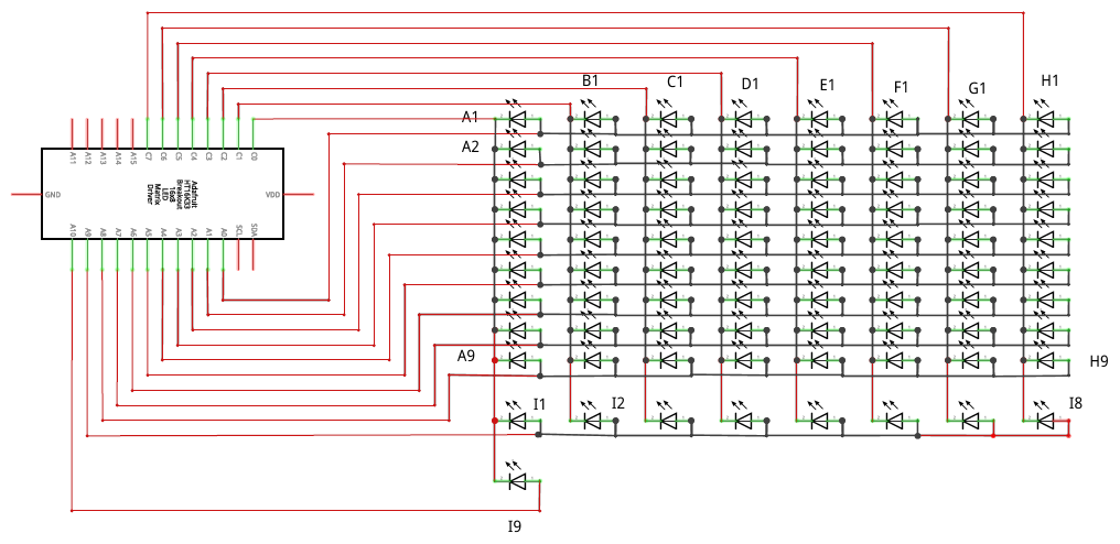
No acabo de entender lo de dejar los I2C libres... En el diagrama de arriba, en la ADAFRUIT,los pines SDA y SCL están libres.
Según
https://docs.circuitpython.org/projects/ht16k33/en/latest/examples.html
los pines SDA y SCL son los I2C.
En el diagrama de arriba las filas/columnas (ánodos/Cátodos) están asignadas a los pines C0 al C7 y los A0 al A9 (El A10 aperece ocupado, pero sobra.)
Pero la pregunta persiste:
¿Cómo conecto FISICAMENTE las dos placas entre si para transferir datos de ARDUINO a ADAFRUIT?
EDITO:
No quiero que interactúen las dos placas. Simplemente enviar desde ARDUINO la jugada ("e2e4") al ADAFRUIT y luego aqui decodificar mediante un HashMap, o similar, y obtener los leds que el ADAFRUIT debe encender/apagar. No se si la terminología que uso es la adecuada pero sería como pasar por "serial" un texto y luego transformarlo dentro de la ADAFRUIT.
Así es como tengo la placa ARDUINO :
Chess ……….. Arduino
——————————-
Column A –> Pin 9
Column B –> Pin 8
Column C –> Pin 7
Column D –> Pin 6
Column E –> Pin 5
Column F –> Pin 4
Column G –> Pin 3
Column H –> Pin 2
Row 1 –> Pin 10
Row 2 –> Pin 16
Row 3 –> pin 14
Row 4 –> Pin 15
Row 5 –> Pin A0
Row 6 –> Pin A1
Row 7 –> Pin A2
Row 8 –> Pin A3
y este es el programa:
#include <Keyboard.h>

// outcomment one of the above
// a) debug via serial (for developing / testing)
// #define BOARD_DEBUG

// b) create a virtual USB keyboard (for final use)
#define USB_KEYBOARD

// the arduino micro pin connections
// layout depends on the wiring
// for the files, ranks and the ky-012 buzzer
int FILE_A = 9;
int FILE_B = 8;
int FILE_C = 7;
int FILE_D = 6;
int FILE_E = 5;
int FILE_F = 4;
int FILE_G = 3;
int FILE_H = 2;

int RANK_8 = 21;
int RANK_7 = 20;
int RANK_6 = 19;
int RANK_5 = 18;
int RANK_4 = 15;
int RANK_3 = 14;
int RANK_2 = 16;
int RANK_1 = 10;


// array of ranks and files
int FILES[8] = {FILE_A, FILE_B, FILE_C, FILE_D, FILE_E, FILE_F, FILE_G, FILE_H};
int RANKS[8] = {RANK_1, RANK_2, RANK_3, RANK_4, RANK_5, RANK_6, RANK_7, RANK_8};


// holds the current state of the buttons and records
// if a button was pressed
bool STATUS[8][8] = {
  {false, false, false, false, false, false, false, false},
  {false, false, false, false, false, false, false, false},
  {false, false, false, false, false, false, false, false},
  {false, false, false, false, false, false, false, false},
  {false, false, false, false, false, false, false, false},
  {false, false, false, false, false, false, false, false},
  {false, false, false, false, false, false, false, false},
  {false, false, false, false, false, false, false, false}
};

int DEBOUNCE_TIMER[8][8] = {
  {0, 0, 0, 0, 0, 0, 0, 0},
  {0, 0, 0, 0, 0, 0, 0, 0},
  {0, 0, 0, 0, 0, 0, 0, 0},
  {0, 0, 0, 0, 0, 0, 0, 0},
  {0, 0, 0, 0, 0, 0, 0, 0},
  {0, 0, 0, 0, 0, 0, 0, 0},
  {0, 0, 0, 0, 0, 0, 0, 0},
  {0, 0, 0, 0, 0, 0, 0, 0}
};


void setup()
{
  // put your setup code here, to run once:

  /*
    Approach that was used in Berger's Solus chess (but here for tactile switches)
    ~~~~~~~~~~~~~~~~~~~~~~~~~~~~~~~~~~~~~~~~~~~~~~~
    - Connect the rows to 8 pins of the microcontroller, setting them as OUTPUT, and initializing them all to '1' (High).
    - Connect the columns to 8 pins of the microcontroller, setting them all as INPUT with pull-up resistor enabled.
    - Set to '0' (Low) one row and read the value of all columns. Do the same with the other seven rows, one by one.
    - In every full sampling of the board (of the 8 rows), we obtain a matrix of 8 x 8 bits.
    - Detecting changes that occur in the matrix at every sampling, we can know what piece was moved.
    ~~~~~~~~~~~~~~~~~~~~~~~~~~~~~~~~~~~~~~~~~~~~~~~
  */
  pinMode(RANK_1, OUTPUT);
  pinMode(RANK_2, OUTPUT);
  pinMode(RANK_3, OUTPUT);
  pinMode(RANK_4, OUTPUT);
  pinMode(RANK_5, OUTPUT);
  pinMode(RANK_6, OUTPUT);
  pinMode(RANK_7, OUTPUT);
  pinMode(RANK_8, OUTPUT);

  pinMode(FILE_A, INPUT_PULLUP);
  pinMode(FILE_B, INPUT_PULLUP);
  pinMode(FILE_C, INPUT_PULLUP);
  pinMode(FILE_D, INPUT_PULLUP);
  pinMode(FILE_E, INPUT_PULLUP);
  pinMode(FILE_F, INPUT_PULLUP);
  pinMode(FILE_G, INPUT_PULLUP);
  pinMode(FILE_H, INPUT_PULLUP);
#ifdef BOARD_DEBUG
  Serial.begin(115200);
  Serial.println("Arduino Chess Board");
#endif
#ifdef USB_KEYBOARD
  Keyboard.begin();
#endif
}

int reset_timer = 0;

void loop()
{
  for (int i = 0; i < 8; i++)
  {
    int rank_i = RANKS[i];
    digitalWrite(rank_i, LOW);
    for (int j = 0; j < 8; j++)
    {
      int file_j = FILES[j];
      int val = digitalRead(file_j);
      if (val == HIGH)
      {
        // val == HIGH: field is not pressed
        if (STATUS[i][j]) {
          // active, check if we are below threshold
          if (DEBOUNCE_TIMER[i][j] - 1 < 2) {
            STATUS[i][j] = false;
          }
        }
        if (DEBOUNCE_TIMER[i][j] > 0) {
          DEBOUNCE_TIMER[i][j] = DEBOUNCE_TIMER[i][j] - 1;
        }
      }
      if (val == LOW)
      {
        // val == LOW: field is pressed
        // val == HIGH: field is not pressed
        if (!STATUS[i][j]) {
          // not active, check if we are above threshold
          if (DEBOUNCE_TIMER[i][j] + 1 > 6) {
            STATUS[i][j] = true;
            char s[] = "a1\n";
            s[0] = 97 + j;
            s[1] = 49 + i;
#ifdef USB_KEYBOARD
            for (int m = 0; m < 2; m++)
            {
              Keyboard.write(s[m]);
            }
#endif
#ifdef BOARD_DEBUG
            Serial.println("button press");
            Serial.println(s);
#endif
          }
        }
        if (DEBOUNCE_TIMER[i][j] + 1 < 9) {
          DEBOUNCE_TIMER[i][j] = DEBOUNCE_TIMER[i][j] + 1;
        }
      }
    }
    digitalWrite(rank_i, HIGH);
  }

}