The resistors on the LEDs are indeed too high, but that does not explain the low analog readings of the TMP36. Check your connections to the sensor again. Maybe try putting it in a different spot on your breadboard. Could be a faulty sensor as well.
@alto777
You're right! That's not the entire code. I have tried to copy it in Autoformat, but it cut off on some point and don't show the code entirely. I don't know why.
const int sensorPin = A0;
const float baselineTemp = 20.0;
void setup() {
  Serial.begin(9600);  // open a serial port
  for (int pinNumber = 2; pinNumber < 5; pinNumber++) {
    pinMode(pinNumber, OUTPUT);
    digitalWrite(pinNumber, LOW);
  }
}
void loop() {
  int sensorVal = analogRead(sensorPin);
  Serial.print("Senor Value: ");
  Serial.print(sensorVal);
  // convert the ADC reading to volatge
  float voltage = (sensorVal / 1024.0) * 5.0;
  Serial.print(", Volts: ");
  Serial.print(voltage);
  Serial.print(", degrees C: ");
  // convert the voltage to temperature in degrees
  float temperature = (voltage - .5) * 100;
  Serial.println(temperature);
So... the code seems to work fine well enough so we can focus on the sensor
Just now the only ideas that occurs to me are that you have a bad sensor, or you have inadvertently picked out a transistor or other temperature sensor of a different kind, both of which may look just like the LM60CIZ/NOPB the circuit is designed for.
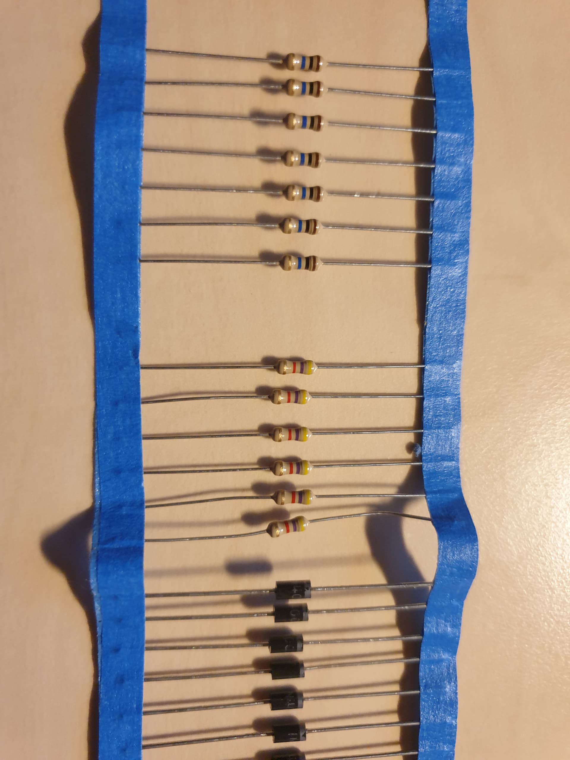
The gold band is the last band, start from the opposite end to gold.
The gold band is the 5th on a resistor with 5 bands, and 4th on a resistor with 4 bands.
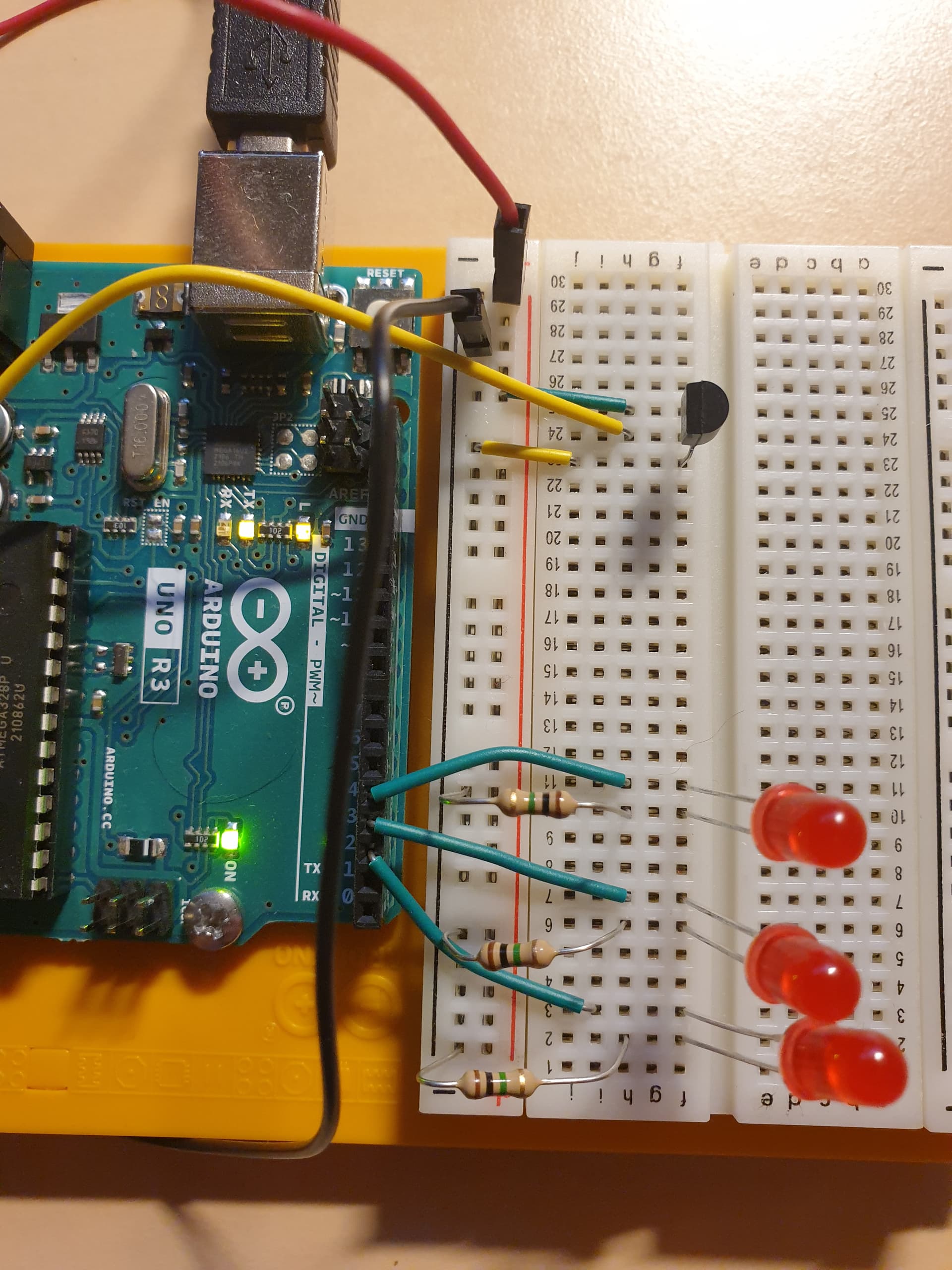
The resistors you are using look like 1M ohm to me, and if so the LEDs would never be illuminated.
I find it difficult to read values on the tiny resistors I typically use for Arduino circuits. The three in my photo are all 220 ohms but only one of them is coded clearly. Even after removing my glasses and peering from six inches away I still reach for my DMM to remove any risk of mistake.
Not sure of your experience level? Do you not have a cheap digital multimeter?
It would have been a good idea to show the source of your circuit:
Or so very dim!. But the sesnor reading, and the temperature derived from it are printed, and the values printed are wrong.
The LEDs are an entirely separate problem, addressing which problem will make more sense once the sensor is reporting plausible values.
I can already guess that the LED portion may need some tweaking, that or the formula used to get from raw sensor reading to temperature.
@janosch1 in neither photo can the markings on the real component be seen.
Please look closely and post all numbers and letters on the part here.
You could try moving the sensor on the breadboard a few holes to the left or right so as to avoid all three rows you are using now. No, you shoukd not have to. Yes, at this point the time that would take is worth it to eliminate an unlikely possibility.
If you have a voltmeter, measure the supply voltage that the sensor is actually getting by placing your probes one directly on the left leg, and one on the right leg. See if you have 5.0 volts as it appears you need, and shoukd have by looking at you photos.
I should mention I am rookie and yes I should buy multimeter. So that's on my shopping list now.
"The resistor" is a topic by itself. I find it quite difficult, for me, as a rookie. So, I do know about the colour code, how do I know what's back and front colour band? Why do we have 4 and 5 band resistor?
I should mention I am rookie and yes I should buy multimeter. So that's on my shopping list now.
Yes, I totally go along with you. Resistor it hard to read them particular with no experience to work with them like i have.
Amazing! I did know, that Arduino has YouTube videos. But unfortunately, they aren't showing which resistor the using.
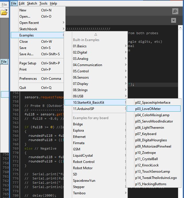
Great! I found the coding setting in the examples of Arduino IDE.