Hi
Im a complete newbie to arduino
Im trying to build a project and need some guidance about all the electronics i need to purchase.
The project consists of
2 stepper motors
2 bidirectional flex sensors
1 arduino
The idea is simple ... when the flex sensor(s) is pushed
The stepper motor(s) will turn in the direction it is programmed to.
The project needs to run Standalone with batteries
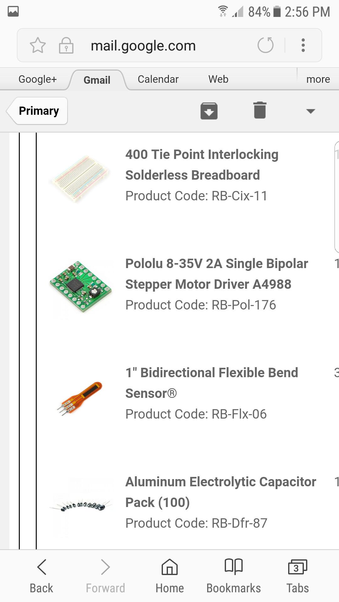
Ive already purchased a few items to get started
But i know i am missing some electronics still.
So im askimg for help on here hopefully someone could point me in the right direction to what else i need to buy so i could get started .
I will post the list of what i already bought in the attachment
Eastbandit23:
The idea is simple ... when the flex sensor(s) is pushed
The stepper motor(s) will turn in the direction it is programmed to.
The project needs to run Standalone with batteries
I don't see a connection between your title and your project spec.
Stepper motors are very inefficient and are not generally suited to battery power - unless you only need the project to run for a short period.
A diagram (even a very rough one) of the project you plan to build would be a great help with our understanding of your project.
Thank you all for such a fast reply
And for the warm welcome.
I am placing the project on an encasing ive poured out of plastic
The motors will be active only for a short time
No more than 20 seconds at a time
However they need to to be idle so that when the flex sensor is pushed the motors will do their jobs ....
I have no experience in Arduino programing and some experience in electronics ( soldering etc.) I am a fast learner so please have patience with me ...
I am ultimately trying to figure out which electronics to buy and if i cant handle everything i will hire someone from my area to help me!
I have drawn a Rough diagram ( i know its not verry professional so please do not laugh at me
Its a project with wheels and sensors im working on
It doesnt have a name ...
Just need to know what i need for this to work
Do you understand the diagram?
Well it would help me to help you if I knew what the hell is was supposed to do.
Do you understand the diagram?
It might make sense to you but it makes no sense to me. You have 2.7V on the stepping motor, but stepping motors should not actually be fed with that voltage, I don't think you understand what the motor specification is telling you. Then there are that red line that randomly goes between the flex sensor and the motors, why?
Don't worry too much as you are not alone. A surprising number of people don't actually want any help, but I do wonder why you bother. When you go to a doctor and he says "what is the problem"? Do you say "not telling you have to guess"? Well that is what you are doing here.
Good luck doing what ever the hell it is you are doing but I am out of here.
The red wire represents connections but i didnt include how the connections should go to the breadboard and then to the arduino etc.
Just drew how the project should work on a fast basis
The red wires are not randomly placed there
They are explaining how they should be activated when the flex sensor is touched
I feel like youve mocked me so far .. so please do leave as you havent been of much help to provide any solutions only asked questions and raised problems
Eastbandit23:
Just drew how the project should work on a fast basis
The red wires are not randomly placed there
They are explaining how they should be activated when the flex sensor is touched
Well, OK, I get that part just as poorly as the rest of the people here, and I'm also still bogged with the question:
WTF is this supposed to do, really?
What is it's purpose?
That determines what hardware you need. How big/strong does everything has to be. How much power involved. How much bending expected. How hard are the pushes going to be. How often. And that are just some questions on the top of my head, ALL OF THEM IMPORTANT FOR SELECTING APPROPRIATE HARDWARE.
Remember we know NOTHING about your project except what you tell us about it. What I see here could be part of some weird art installation, part of a system to evade alien invasion, or maybe even the controls of an underwater rover.
Im working on a top secret experiment for the u.s government in order for the project to avoid a mass human extinction by an extraterrestrial race that have a base on the darkside of the moon
So yes we are working on saving the world here Hehehehe
Look guys all i want is to connect
2 sensors to 2 motors to rotate 2 wheels when the sensor is pushed
ITS NOT ROCKET SCIENCE
I have 2 2.7 stepper motors
I want to connect them as the diagram says
To 2 bidirectional flex sensors
So that i can move 2 wheels
How strong the wheels move depends on the programmimg does it not?
Eastbandit23:
How strong the wheels move depends on the programmimg does it not?
It depends on 1) the programming, 2) the actual motor power, 3) the type of motor (how many steps per rotation), 4) the size and weight of the wheels, 5) the type of aliens it's meant to kill.
You can try to make a stepper make more and more steps in software but when it doesn't have the power to make the wheels spin that fast, you may break the stepper or it simply doesn't work at all. If what you want to do is turn the wheels faster when you push the rod faster, a stepper is almost certainly not the most appropriate type of motor in the first place.
You asked for "what else do I need to buy", well, again, that depends on the actual parts you have and what you actually want to do with it.
So without you providing detailed info, I'm done wasting my time here.
The stepper is rated 1A, 2.7V. You need an appropriate power supply for this. That's a rather uncommon voltage so likely you'll have to build your own. It needs an external controller that can work at 2.7V and provide 1A to the motor.
Your Arduino runs on 5V (maybe 3.3V). That's a separate power supply. You may need a level shifter to bring down the Arduino voltage to the 2.7V the stepper controller has to operate on.
Now what's still missing is info on those flex sensors.
If there is any easier way to build a project using different motors to cope with any other batteries and work with this flex sensor
I am open to hear it and accept new ideas.
Eastbandit23:
The motors will be active only for a short time
No more than 20 seconds at a time
However they need to to be idle so that when the flex sensor is pushed the motors will do their jobs ....
The problem with powering stepper motors from a battery is that they consume the full current even when they are idle. If they don't they lose position.
wvmarle:
The stepper is rated 1A, 2.7V. You need an appropriate power supply for this. That's a rather uncommon voltage so likely you'll have to build your own.
This is not a correct analysis. The nominal voltage of a stepper motor is irrelevant. Stepper motors work better when powered with high voltages through a specialized stepper driver that can limit the current to protect the motor. See Stepper Motor Basics
Mmm... It seems I missed some bits and pieces about steppers Thanks for the correction.
Eastbandit23:
This here is the flex sensors i have
Can't find info on how to connect them on the page you linked to.
If there is any easier way to build a project using different motors to cope with any other batteries and work with this flex sensor
I am open to hear it and accept new ideas.
Well, without an answer to the question of what application this has, no further suggestions here.