Hello, I am using an arduino nano to generate a 0 to 100 duty cycle PWM at 31kHz. I also need power decoupling, I used PC817, but I noticed that when the frequency is standard 490Hz, the PC817 optocoupler works well, but not at 31kHz, I think because the optocoupler is slow (connection diagram V1). I decided to use a 6N137 optocoupler, but I can’t understand correctly, did I draw a connection diagram (connection diagram V2)? I need the PWM_out pin to be pulled to ground. Help please, thanks.

On a 6N137, Pin 5 is Gnd and Pin 6 is the output.
Try this (similar to their test circuit fig 14 ...

Thanks, I saw this circuit in the datasheet, but the PWN_out will be pulled up to +5 volts, and I need to pulldown(GND). Any ideas how to do it?
Maybe:
pwmOut = 255 - pwmIn;
?

V3 would need @JCA34F s suggestion for the output duty to follow the input duty in software.
V4 : output follows input, only draws current during PWM on time (duty).
I believe PWM can be inverted with proper timer register settings, but that's above my pay scale ![]()
Oh @johnwasser.
In V3, flipping the duty in code to invert would work, but would have the characteristic of the on time occurring at the end of the PWM period, rather than at the beginning.
V4 requires no inversion (I recommend this version). Also, it only draws current during the PWM on time (duty).
Thanks, this is necessary so that if the microcontroller is turned off, but another power supply is turned on, there is no +5 volts at the pwm_out output, since pwm_out controls the A3941 Allegro driver, and the driver controls the H-bridge for motor. Now motor should not start when the controller is turned off. I'll try and post the result, thanks again.
You can use the schematic from #3 (and i would use a higher value resistor for the pullup) and invert the signal using a general purpose NPN transistor.
Connect pins 7 and 8 to 5V, and pin 5 to ground. Pin 6 is your PWM output.
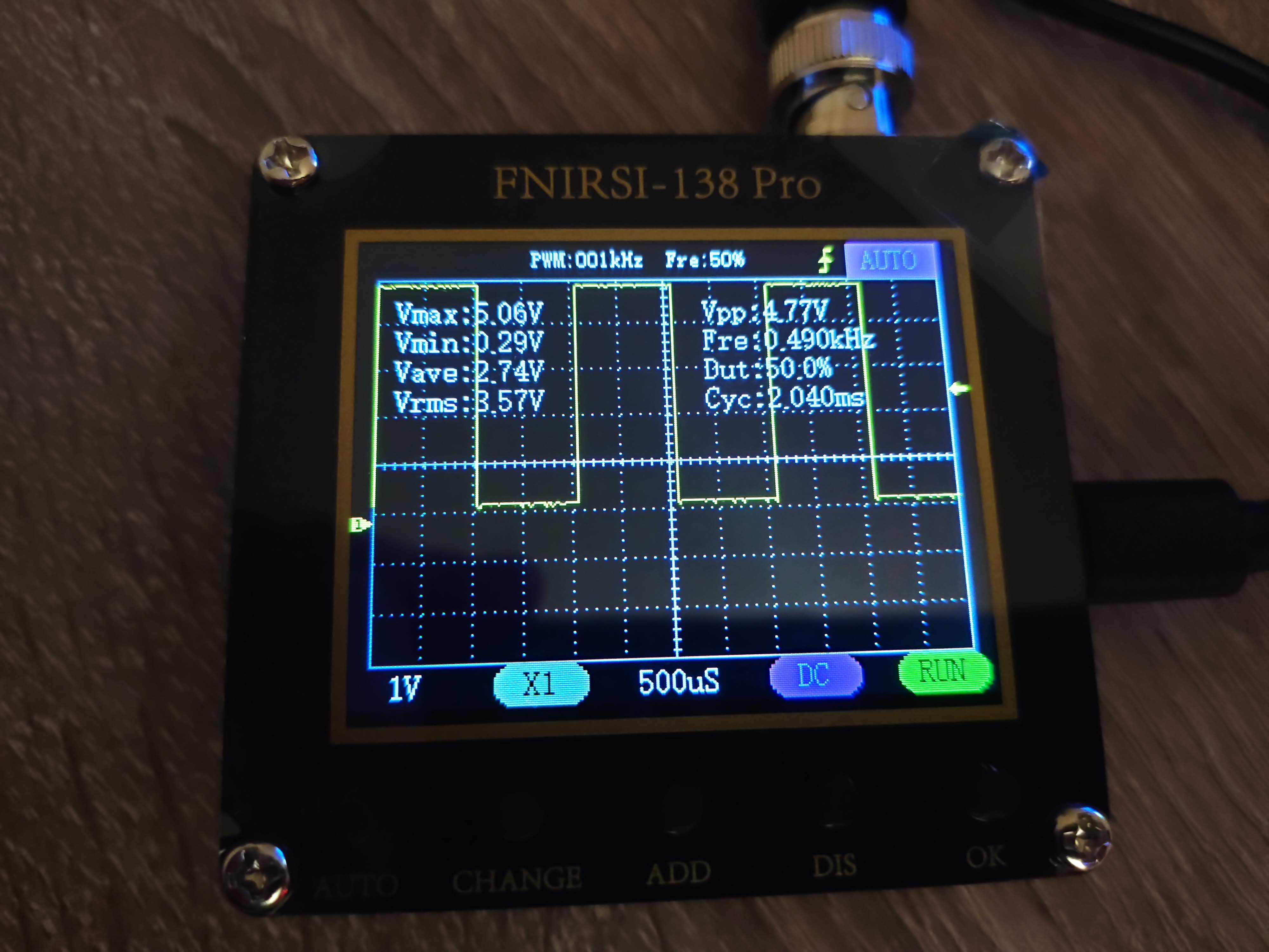
I used V3 and V4. I also purchased a small oscilloscope fnirsi-138 pro.
Used analogWrite(9, 127); (50%)
result 3 has Vmax 5v, Vmin 0.3v, this is great, but when the microcontroller is turned off, there will be +5 volts here due to the pull-up to the power supply, and I need 0 when the microcontroller is turned off.
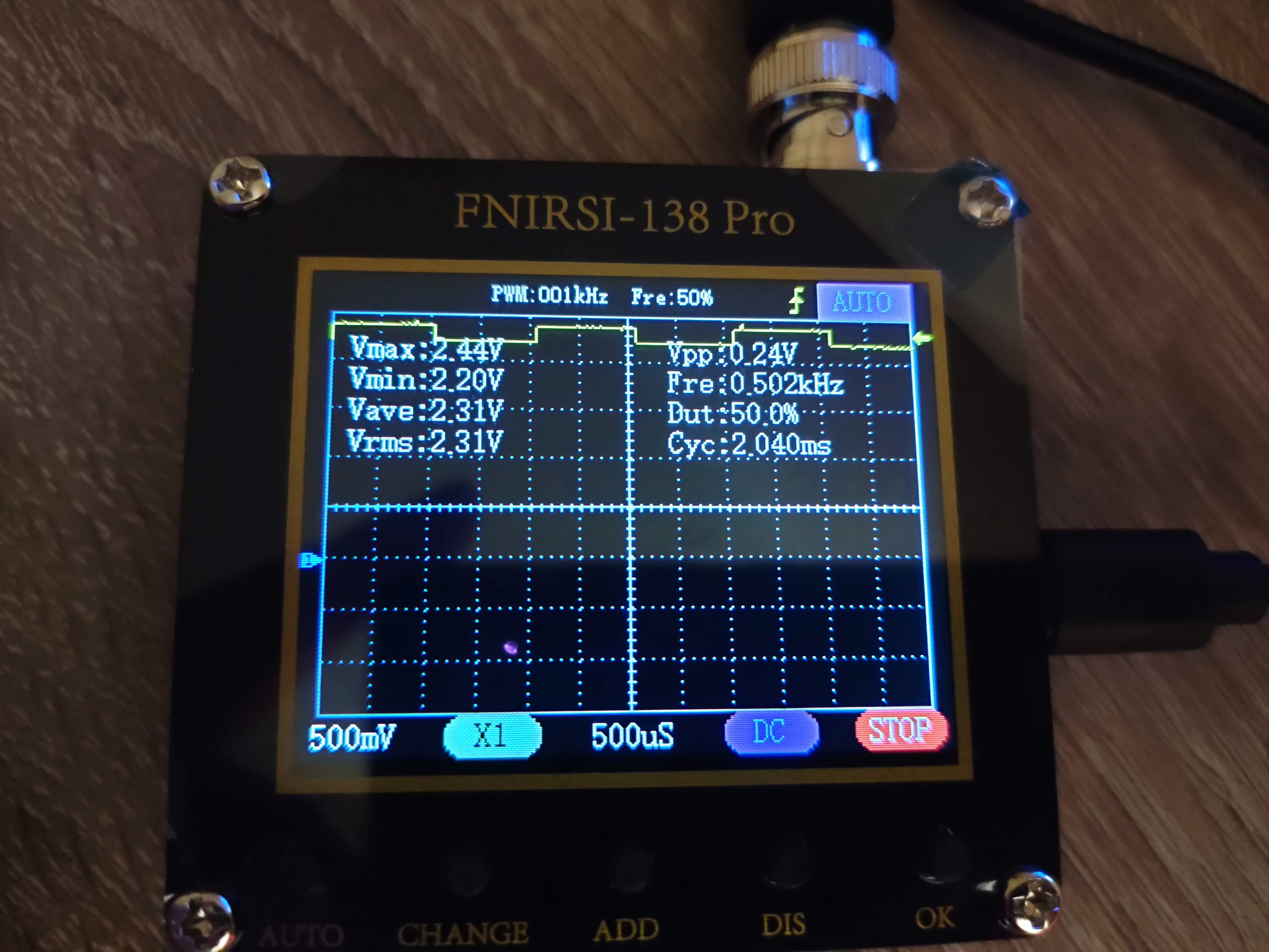
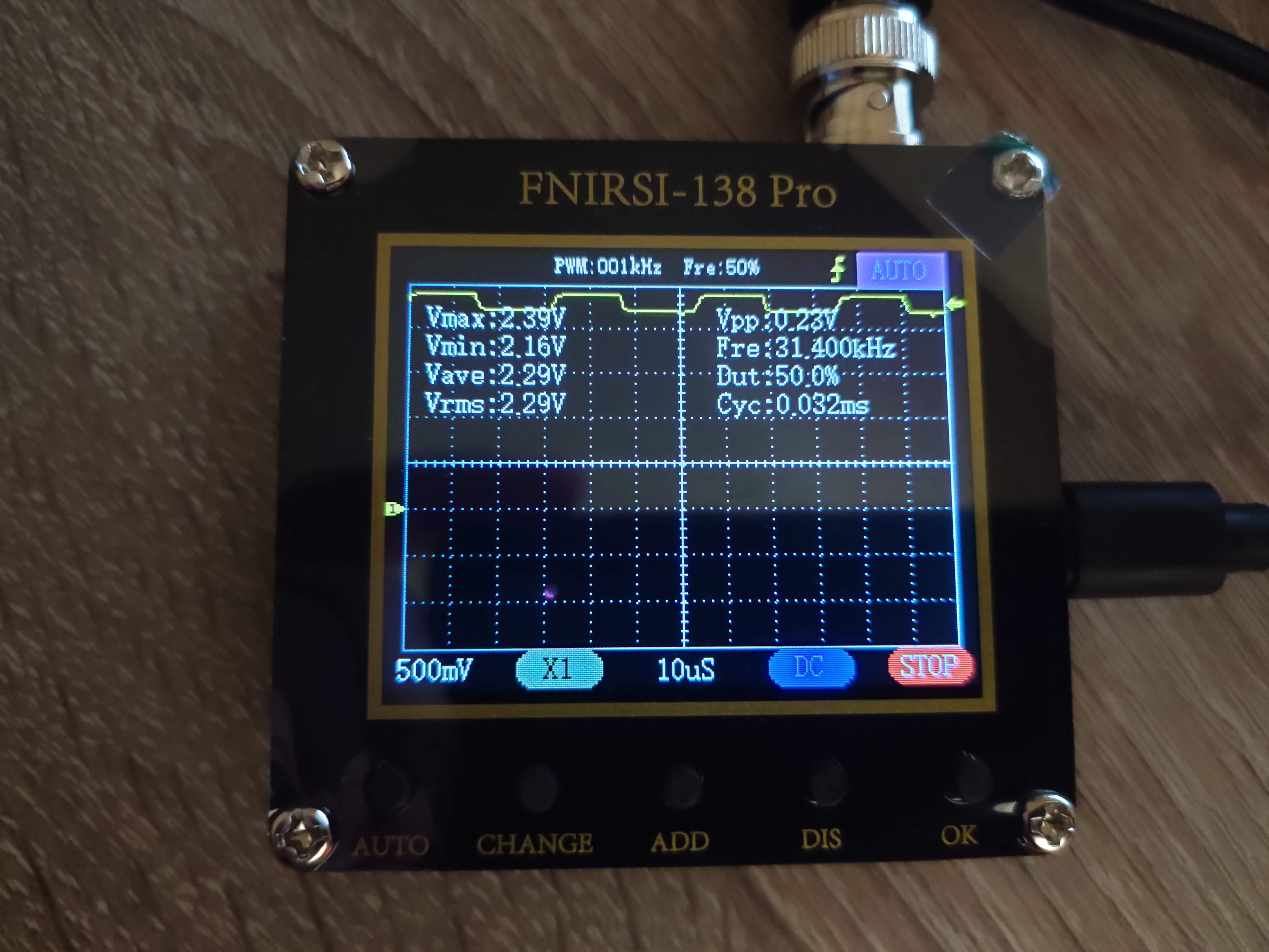
result 4 has Vmax ~2,4v, Vmin ~2,2v, this range does not suit me, I need from 0 to 5 volts, when the microcontroller is turned off, it will be 0 here because of the pull-down to the ground, which is what I need.
how can I get from ~0 to ~5 volts and so that when the microcontroller is turned off it will be 0 due to a pull-down to the ground?
connection V3:

connection V4:

result V3 490Hz:
result V3 31kHz:

result V4 490Hz:
result V4 31kHz:
I guess with the 6N137 having high speed logic on the output side, it can't be pulled up and used as a high side driver as you could with a phototransistor like the PC817. The cutoff frequency of the PC817 is 81kHz, so there should be enough bandwidth to work with a PWM frequency of 31 kHz.
Try this circuit:
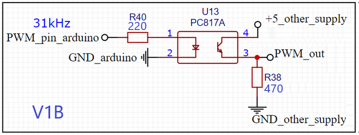
V1B, here is what i got when on PC817A, duty 50% arduino , out PC817A ~72%. any ideas why that is?
i think can try use V3 + 74HC14D(inverting schmitt trigger), and solution to my problem ?

OK, I guess your part is within spec, but isn't at the faster end of this:
At 31.25kHz, 50% duty represents 16μs. The error is 22% duty which is 7.3μs. (the fall time is 7.3μs longer than the rise time).
1 Like
Hello pantiak,
Here s why you see different duty cycle. It will be little bit theoretic, sorry.
The photodiodes works in 2 modes, photoconductive and photovoltaic. In the first mode the diode is reverse biased. But every reverse biased diode has capacitance. To get high current transfer ratio CTR in the photocouplers the diodes there are relatively big and with big capacitance. Here is simplified diagram:
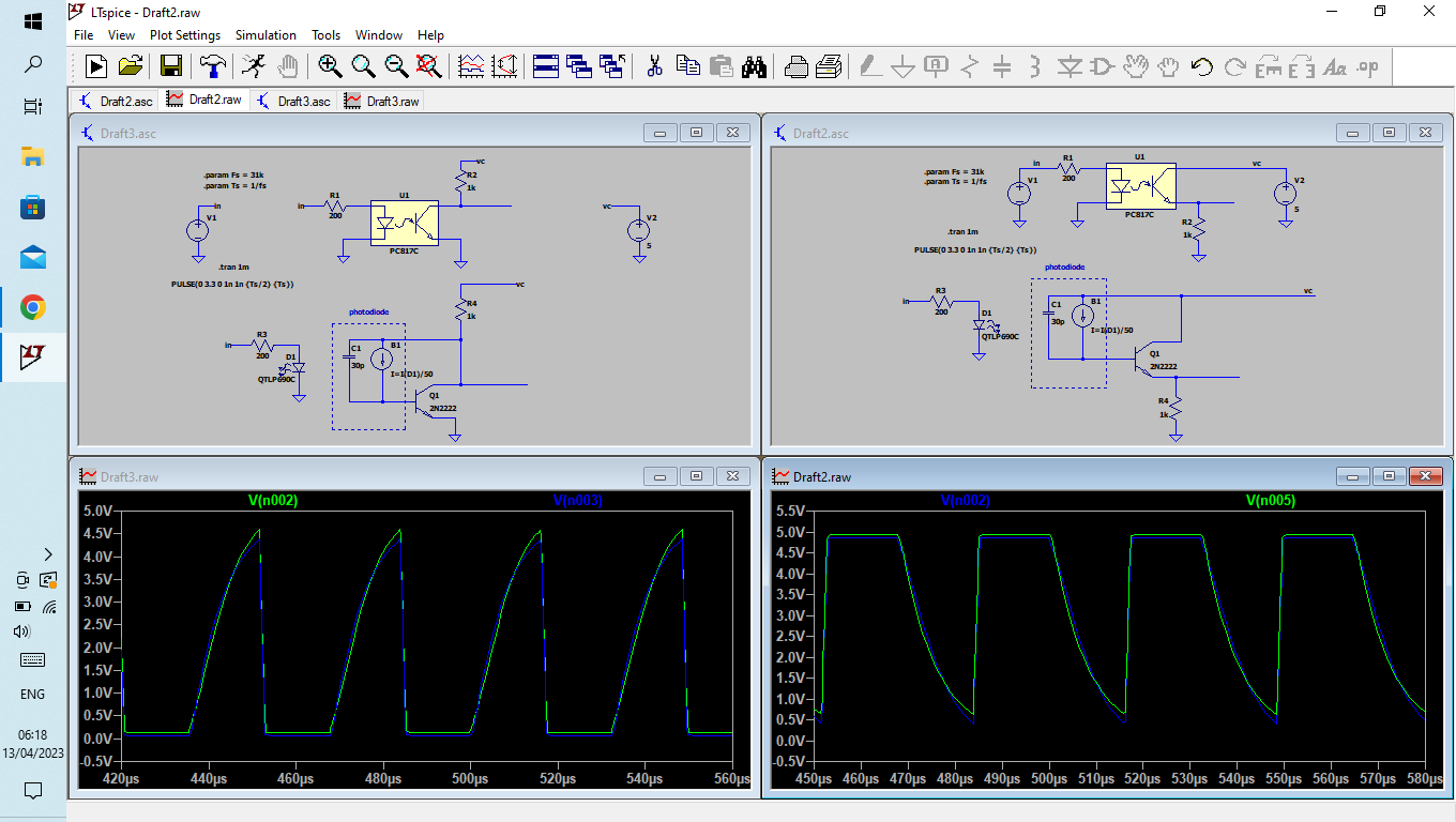
Now, if the signal is taken from the collector, the transistor is in common emitter and the input impedance is relatively low (kΩ). This will prevent the capacitor to be charged fast. If the signal is taken from the emitter, the transistor is in common collector mode. The input impedance is high and the cap will discharge slow.
The charge/discharge will depend on the saturation of the transistor and is possible to get 50% duty cycle, but every opto' must be tuned separately. Not a good solution.
Of course it is little more complicated than that.
Use transistor as inverter switch after 6N137.
2 Likes
There's faster opto isolators (photo transistor type), but couldn't find any in stock. I think for high speed and performance, most people switch over to the 6N137 ... it is well stocked and popular. However, being positive logic and with your requirement of not having the output normally high when the IRLED is off, then ...
Yes, or transistor inversion as post #10.

1 Like
This topic was automatically closed 180 days after the last reply. New replies are no longer allowed.