I use a simple script to control a couple of servos which works perfectly with a couple of other boards, an Uno and a Mega. I was just trying out my new R4, and noticed that at 90 degrees, there is a significant "jitter" of both servos. Same at 45 degrees, but not 0 or 180.
I've tested this with several different means of powering the board, including a laptop on battery, so there should be no AC ripple sneaking in.
In the code:
int start1=90;
int stop1=165;

#include <Servo.h>

Servo servo1;
Servo servo2;
int pos = 90;

Serial.begin(9600);
servo1.attach(6);
servo2.attach(7);
Servos powered from the onboard regulators can jitter, when they work at all, on other Arduinos. I have no direct R4 experience. Do you have separate servo power?
Here's what I have. I was under the impression that the command was only being sent each time I press the button:
#include <Servo.h>

const int button = A0;
int start1=90;
int stop1=110;

Servo turnout1;
Servo turnout2;


int pos = 90;    // variable to store the servo position

void setup () {
Serial.begin(9600);
turnout1.attach(9);
turnout2.attach(10);

}
  enum SWITCHSTATES
  {
    ST_OFF1,
    ST_OFF2,
    ST_STRAIGHT,
    ST_TURN,
  };
  SWITCHSTATES switchState = ST_OFF1;

  void loop() {
    int buttonRead = analogRead(button);
    delay(200);
    switch (switchState)
    {
      case ST_OFF1:
        switchoff1(buttonRead); //sets up changes to ST_OFF1
        break;
      case ST_OFF2:
        switchoff2(buttonRead); //sets up changes to ST_OFF2
        break;
      case ST_STRAIGHT:
        switchstraight(buttonRead); //sets up changes to ST_STRAIGHT
        break;
      case ST_TURN:
        switchturn(buttonRead); // sets up changes to ST_TURN
        break;
    }
  }

  void switchoff1(int buttonRead) {
    turnout1.write(start1);
    turnout2.write(start1);

    if (buttonRead > 500) {
      switchState = ST_TURN; //switches to different state

    }
  }

  void switchturn(int buttonRead) {
    for (pos = start1; pos <= stop1; pos += 1) { // goes from 0 degrees to 180 degrees
      // in steps of 1 degree
      turnout1.write(pos);              // tell servo to go to position in variable 'pos'
      delay(15);
      turnout2.write(pos);              // tell servo to go to position in variable 'pos'
      delay(15);                      // waits 15ms for the servo to reach the position
    }
    switchState = ST_OFF2; //chages to ST_OFF2
  }

  void switchoff2(int buttonRead) {
    turnout1.write(stop1);
    turnout2.write(stop1);

    if (buttonRead > 500) {
      switchState = ST_STRAIGHT; //switches to Straight

    }
  }

  void switchstraight(int buttonRead) {
    for (pos = stop1; pos >= start1; pos -= 1) { // goes from 180 degrees to 0 degrees
      turnout1.write(pos);              // tell servo to go to position in variable 'pos'
      delay(15);
      turnout2.write(pos);              // tell servo to go to position in variable 'pos'
      delay(15);                       // waits 15ms for the servo to reach the position
      switchState = ST_OFF1; //chages to ST_OFF1
    }


  }
Servo jitters are almost always due to an inadequate servo power supply. The Arduino is not a power supply and should never be used for motors or servos.
For two small servos like SG-90, a 4xAA battery pack will work. Don't forget to connect the battery negative to Arduino GND.
I also have a good regulated 5 volt supply here. I'm going to read up some more regarding the power requirements of the R4 Wifi as well. I take it that you should always bond the ground on other devices or equipment with the Arduino when using them.
I also learned something else new - I was just checking with my meter, and sure enough the farther the servo gets from 0 or 180 degrees, the more current it draws!
As a rule of thumb the power supply should be rated for 1 Ampere/servo (for small servos) and 2.5 to 3 A per servo, for MG996R and the like.
It is a good idea to look for the "stall current" specification on a servo product page or data sheet, as it briefly draws the stall current every time it starts moving.
I take it that you should always bond the ground on other devices or equipment with the Arduino when using them.
Yes, ground is the zero voltage reference for signals as well as power supplies.
Why are you using an int from an analog input instead of a digitalRead?
wire your button from the desired pin to gtound. set the pin to INPUT_PULLUP mode and test for if (digitalRead (pin) == LOW) when pressed.
Get rid of the greater than logic and smooth that logic out. When the button isn't pressed the AI may be floating and noisy, triggering your state logic randomly.
I'm a really new beginner at this, and and like many beginners, I often copy bits of code from other places that seem to function without precisely knowing why. My previous experience coding was with BASIC in the 80s, but I am studying.
But to answer you question, I had no idea why I was using an int from an analog input instead of a digitalRead, except I found that line on YouTube, and that guy got it out of a 2018 article in a model railroad magazine.
Greatly appreciate this. I'll change it. Now that it's running well on the R3 uno, I have the luxury of carefully going over the whole script, and see if I can figure out the proper way it should be written. I was probably getting away with murder, because the R3 device doesn't require as much current. I'll also clean up the hardware configuration with a regulated 5v servo supply with sufficient output.
The code you have is needlessly complex. Start simple. Turn an led on with button push, then add hw one item at a time, testing as you go. Lift code from the device examples and add to your code-base one item at a time. Don't try to add more than one hw/sw item at a time. Build on a solid foundation and you'll be making robot monsters in no time!
Others have mentioned power issues. Build one of these:
About $15 USD, under an hour to fab. Requires soldering.
Do you have a 3D printer? I have cable and mounting .STL files for free over on cults3d.com
At the moment, the model railroad project is working flawlessly with 2 servos and a couple of 3 led signal lights using the R3 Uno, so I have the luxury of analyzing my code, No problems with the R3, but I can certainly see where I'll run into issues when I'm eventually using 6 or 10 servos and more sensors and signals on the layout.
As a beginner, I got instant gratification by borrowing someone else's working script without fully understanding why some of it works. :-).
Hello everyone,
I'm having problems with the Uno R4 wifi and two servo motors. The servo motors are connected to an external 6 V power supply (4 AA batteries connected in series) with GND shared with the board. Each servo has a capacitor of 100 to prevent noise. Even so, the servos are unstable. I'm controlling the servo motors via WIFI via OSC. Does anyone have any tips they can share to solve this problem?
a) Power - Typically AA batteries do not give very much current, and often times even worse, how they are connected to each other. Often times they have very small gauge wire and the contacts between the wires is not great.
b) Servo library - I have not used it on these boards, but on other boards it was very susceptible to jitter, due to inconsistent pulse widths for going to the servos. Often caused by the processor servicing other interrupts, which changes the timing.
For the fun of it, recently I ported the PWMServo library by PaulStoffregen to run on these boards.
Which I mentioned up on the thread:
The code is up in my fork/branch: GitHub - KurtE/PWMServo at UNOR4
At some point I will issue a Pull Request back to Paul, but was sort of waiting to see if anyone tries it out and it works for them.
The nice thing about this approach, is the servo pulses are generated by PWM (Timer), without the need to process interrupts. So it can help remove the jitter.
I have since learned a great deal, and everything is now powered with a 500 watt computer power supply.
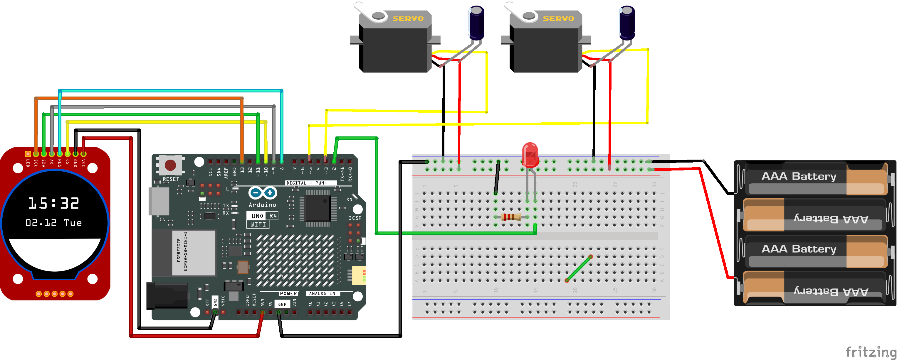
Here's the finished schematic, with the exception that no voltage is coming from the Arduino, and everything runs off the well regulated computer power supply.
Everything works perfectly! This was a fun project!
a) Power - Typically AA batteries do not give very much current, and often times even worse, how they are connected to each other. Often times they have very small gauge wire and the contacts between the wires is not great.
b) Servo library - I have not used it on these boards, but on other boards it was very susceptible to jitter, due to inconsistent pulse widths for going to the servos. Often caused by the processor servicing other interrupts, which changes the timing.
For the fun of it, recently I ported the PWMServo library by PaulStoffregen to run on these boards.
Which I mentioned up on the thread:
The code is up in my fork/branch: GitHub - KurtE/PWMServo at UNOR4
At some point I will issue a Pull Request back to Paul, but was sort of waiting to see if anyone tries it out and it works for them.
The nice thing about this approach, is the servo pulses are generated by PWM (Timer), without the need to process interrupts. So it can help remove the jitter.
First of all, thank you for your quick reply to my request for help. To make my problem clearer, I'm sending you the circuit diagram and its code. My project consists of creating a robotic module to control a video camera that will transmit images by streaming to the patch in Max/msp. Control will be by OSC via WIFI from Max/msp commands. One of the servos will be used to move the camera and the other to move the camera's focusing system. For this project I need stable movements to guarantee video quality. My knowledge of arduino is basic, so for programming I often use Chatgpt to generate code.
Based on this description, I would ask you to give me advice on how to overcome the barriers I face. Thank you very much for your help!