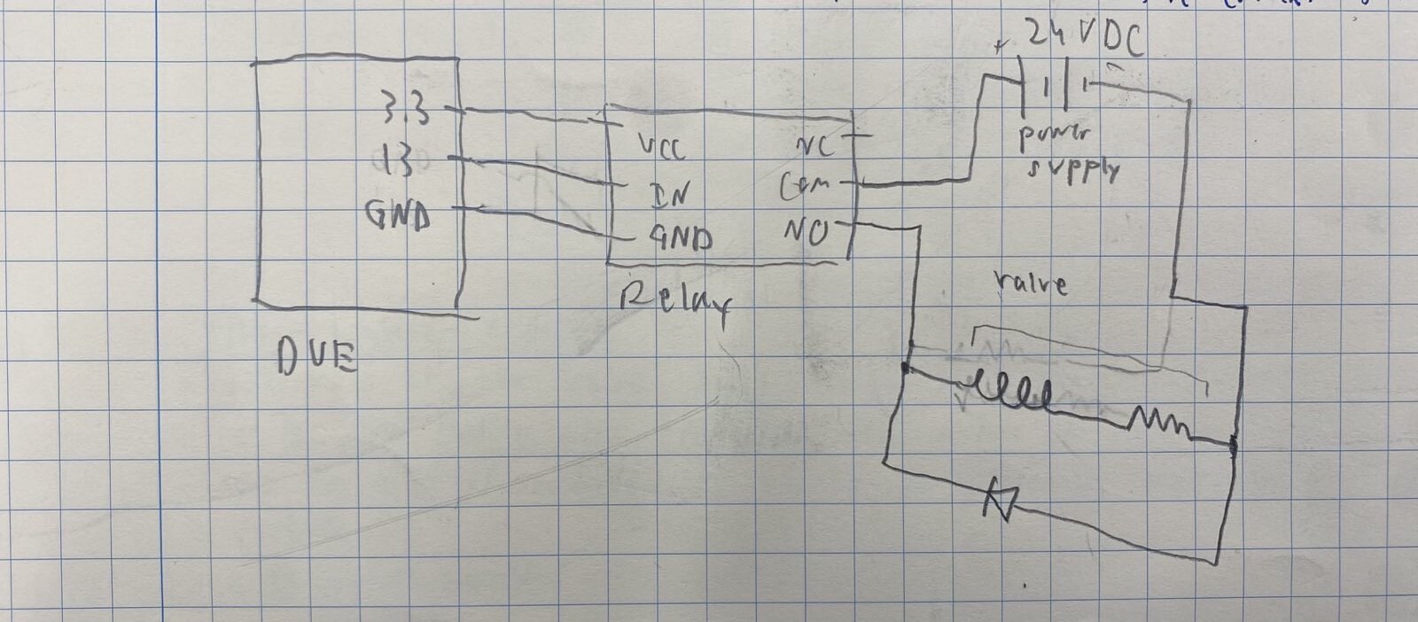
I'm using an Arduino Due to open and close a relay that toggles power to a valve. When the valve is powered, the Arduino will occasionally randomly disconnect from the computer, here is what I know
It only happens when the other side of the relay is powered
I cannot get it to happen reliably, sometimes it will work perfectly for 100 opens/closes and other times it will fail the first time I try and close the valve
I have swapped out the Due for another Due, and the Relay for another copy, the wires connecting the relay and the Due, the power supply, the valve, the wiring between the relay, valve, and power supply, as well as the housing, and the issue still happens
The relay is rated for the power being handled on the other side.
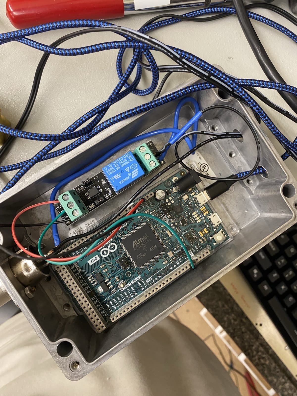
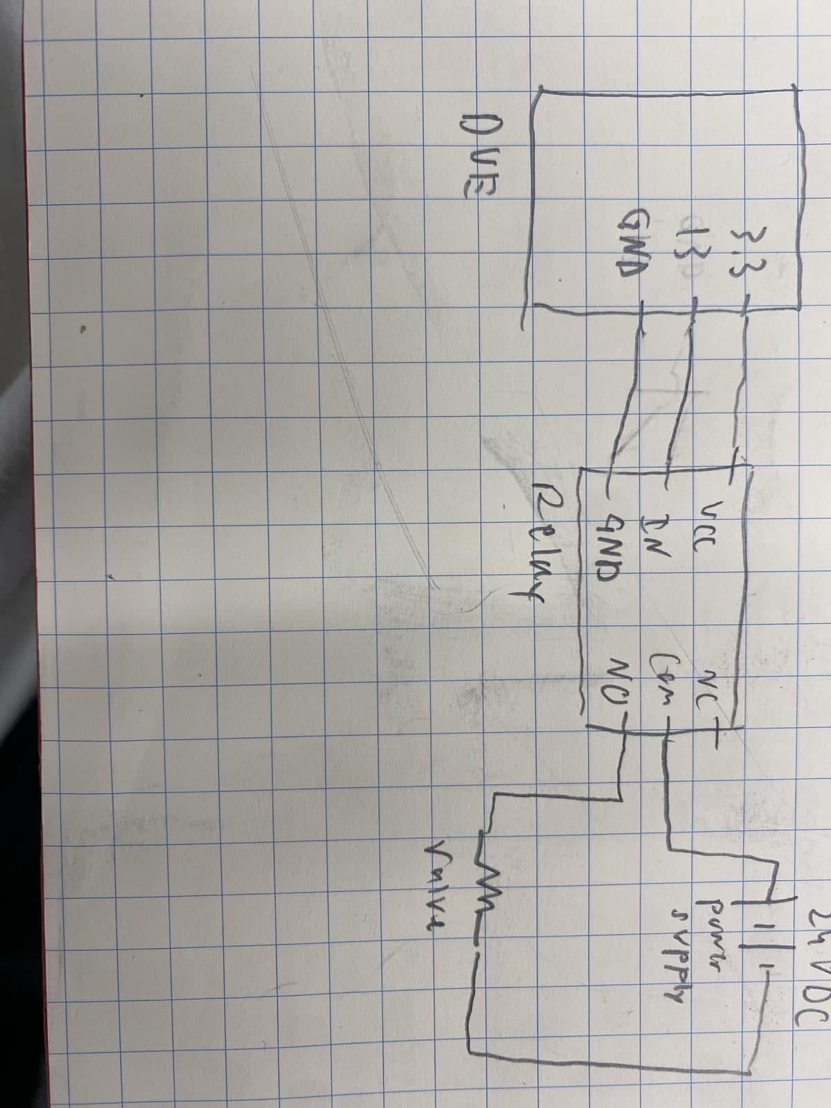
I've included an image of the setup, the circuit diagram, and the code. Any help would be greatly appreciated as I am at a loss of what to do
bool VS = false; // Valve Status

void setup() {

  pinMode(13, OUTPUT);  // Make Pin 13 Output
  digitalWrite(13, LOW); // Make Pin 13 OFF

  Serial.begin(9600); // opens serial port, sets data rate to 9600 bps 8N1
}

void loop() {
  char RxedByte = 0;

  if (Serial.available()) {
    RxedByte = Serial.read();

    switch(RxedByte) {
      case 'o': //lowercase letter O for open
        if (!VS) {
          digitalWrite(13, HIGH);
          VS = true;
          Serial.println("Valve opened");
        } else {
          Serial.println("Valve is already open");
        }
        break;
      case 'c': //lowercase letter C for close
              if (VS) {
                digitalWrite(13, LOW);
                VS = false;
                Serial.println("Valve closed");
              } else {
                Serial.println("Valve is already closed");
              }
              break;
      case 's': // s for status
        // Report status of valve in one message
        char buffer[100];  // Buffer to hold formatted string

        // Format the status message
        sprintf(buffer, "Valve status: %s",
                VS ? "Open" : "Closed");

        // Print the formatted message
        Serial.println(buffer);
        break;
    }
  }
}
the code was repurposed from a different system that handled several LEDs instead of a single valve, which is why the status command is formatted a bit strangely
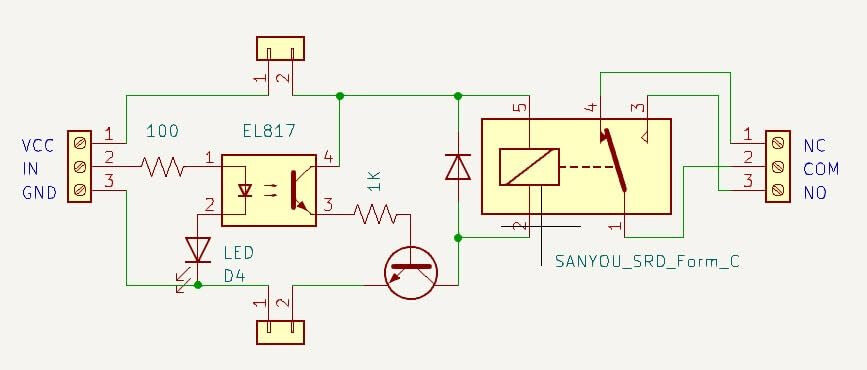
A link (that includes a schematic) to the relay module you're using would be helpful. I'm curious just how much current it's asking for from the Due's 3.3V supply.
Valves are usually inductive, Install a kick back, free wheel, diode across the load!
Relays are specified for a maximum AC, or DC, voltage and they are usually different. They are also specified for current in the same way. They are not spcified for a certain power.
The response will get truncated and the orange " not connected. Select a board and a port to connect automatically." will show up above the serial monitor in the IDE. I will also sometimes hear the USB disconnect noise and it will disapear from device manager, but that doesn't always happen. It will then reconnect by itself
do you mean a flyback diode(thats what came up when I googled)? I'm inexperienced when it comes to circuits so I'd really appreciate if you could elaborate
Apologies, I was using words wrong. What I should've said was "The DC voltage and Current going across the relay are below the maximum values specified"
I'm not quite sure this is what you're asking but: I stuck an ammeter between the 3.3V port and the VCC line, it measured 0.108A. The issue only occurs when closing the valve, which is opening the circuit, which would mean a stoppage of current no?
Already tried out of enclosure, none of these wires are AC, have tried multiple USB cables.
Think like this: Note the direction the current is flowing when the relay is active, ON. A magnetic field exist in the valve and when the relay goes OFF that energy wants to maintain the current flow. This causes sparcs in the relay, and RF type noise that tilts the controller.
Install the diode so this switch off current has a path to go!
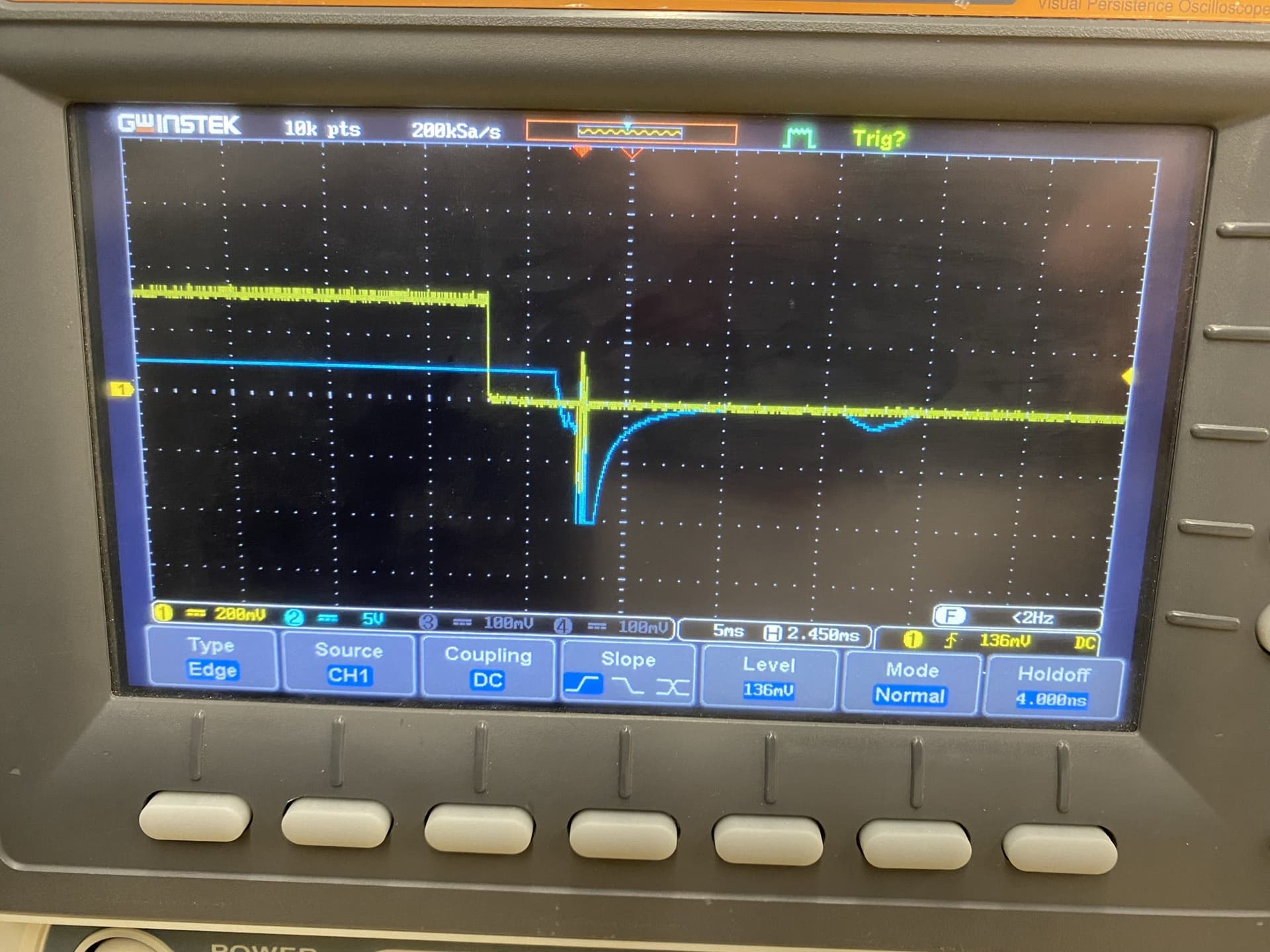
I checked with an oscilloscope, the yellow line is the voltage from pin 13 as I close the valve, the blue is the voltage across the valve(ignore the units in the bottom left, they are wrong). I think it is very clear from the messy behavior that there is backfeed from the valve. I am going to do two things, follow Railroader's advice and add a flyback diode, and look for a better relay that has one already built in, as I need to make several of these. I'll report back when this is done.
From the Due page under Tech specs: DC current for 3.3Vpin 800mA. Also the issue happens when the relay is being opened, ie, when power is being turned off
Just to make sure I am going to do this correctly, the Diode should be connected like so?
The diode will not see any 24 volt, only the current flow through the coil and that is for a very short time. Current x 0.7 volt x a few ms makes a very low power discipation.
Hi, @reedjc
Look at this image.
Move wire A over to be next to wire B, that is to keep the load wire AWAY from the controller.
Tidy up wires C so that they do not intermingle with the load and power wires.
I would change the layout.
Turn the relay module around and have the load and its power wires come in on the left side, so that the load current goes NOWHERE near the controller.
The signal wires to the relay module will be then at the other end, AWAY from the load wiring.
That looks like a metal case, have you got it grounded, at least to the DC supply negative?
Tom..
PS. Can you see why the system resets? Load power wires with 0.4A next to control wires with approx 1/100 of the 0.4A current running through them.