Why does my Arduino not work correctly when I disconnect the USB?

Greetings, All!

I'm still learning a lot about Arduino UNO and friends. I'm working on some Halloween projects and one of them has me stumped.

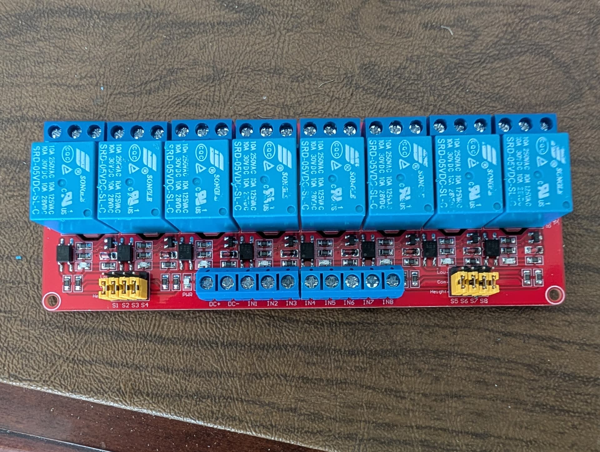
My UNO is VID 2341, PID 0043. ( I've got the serial number if it's a help). I have the UNO connected to an 8-relay board (5 VDC control, 12 VDC through the relays). Each Relay is activated from a port on the UNO (outputs 3,4,5,8,9,10,11,12). The relay controls 12 VDC LED lights. The relay board gets 5 VDC from the UNO power points on the UNO. There are two servos, one to open the front door (output 6) and the Hangman (Output 13) handle the command, power from a 5 vdc terminal on the power bus. The relay operating power comes from the UNO 5 vdc and GND ports on the board. (RELAYS are 5 vdc coil and 12vdc load). The hangman power is sourced from a 12 vdc to 5 vdc converter on the bus.

When I was testing and working to get the sequence exactly the way I wanted it, I was connected to the laptop via the UNO USB port. I even had the 'Serial' function set up so I could see where the program was during testing. (a nice feature BTW for troubleshooting!). When I was satisfied that it was working like I wanted it, it operated for most of a couple of days with no issues. The haunted house is about 18" wide and 13" deep doll house we rescued from the trash man.

Since the 12 vdc source was connected the whole time, as well as the 12 vdc power plug on the UNO (12 + in center, 12- on outside), I unplugged the USB from the UNO and let the program continue. I also tried resetting it. What happens is the hangman sequence is supposed to turn on a light to show the hanger isn't there, the light turns off, the servo swings the hanger out, the light comes back on. The light goes off, the hanger swings back out of the window and the light comes back on to show the hanger is gone. Light goes off and other things go on.

When the USB is disconnected, the servo for the hanger swings out and then right back, and a light in another area of the 'house' turns on and off. The other servo (door) moves faster and slower as it works. Not the same type of operations when it's plugged into the usb.

I'm really stumped on why this isn't working the same when it's unplugged from the laptop. Obviously, I won't be able to leave my laptop connected to the UNO in my front lawn during Halloween.

Any ideas on how to make this work? I can share the program if it would help.

Thanks,

Larry

Usually, problems related to differences with/without USB power originate in the wiring and/or the capabilities of the external power circuit, not the software. So, a clear, properly annotated schematic (not just a wiring diagram) is essential. No one is likely to sort through several paragraphs of descriptive text to try and discern where in all that lies the wiring or source problem, I'm sorry to say, so you'll have to do the work of producing a schematic; pencil on paper, photo of paper is more than adequate, provided your photo is high enough resolution that your text is legible.

2 Likes

As you post the annotated schematic for @camsysca consider the following.

Gil's Crispy Critter Rules for Processor Hardware:

  1. Rule #1: An Arduino is NOT a Power Supply!

  2. Rule #2: Never connect anything inductive (motors, speakers) directly to an Arduino!

  3. Rule #3: Avoid connecting or disconnecting wires while the power is on.

  4. Rule #4: Do not apply power to any pin unless you are certain of what you're doing.

  5. Rule #5: Do not exceed the maximum voltage or current ratings.

  6. Rule #6: Many Arduinos cannot power transmitters directly.

  7. Rule #7: Before powering your project, take a break and double-check the wiring.

  8. Rule #8: Bad soldering makes for project failure.

LaryD’s Corollaries:

  1. Coro #1: When starting out, add a 220Ω resistor in series with both input and output pins to protect against shorts.

  2. Coro #2: Invest in a Digital Multi-Meter (DMM) to measure voltages, currents, and resistance.

Note: Violating these rules can turn your Arduinos into crispy critters. For optimal performance, keep your wires under 25 cm (10 inches).

Additional Tips:

  • The L293 motor driver, though common, is inefficient as it can lose around 3V as heat when driving both legs of a motor. Consider using a motor driver with MOSFET outputs to reduce heat loss and conserve battery power.

  • The nRF24 radios do not work very well when powered with an Arduino even if the 5V adapter is used.

  • For more on powering Arduino boards, explore this guide: Powering Alternatives for Arduino Boards.

1 Like

Hi @lazerlarry !

From the quoted text I understand that you always powered the UNO from a 12VDC using the power jack, is that correct?

If yes, - as the board automatically uses the higher voltage source - USB should not have provided power to the UNO. Hence removing the USB plug should not effect the power supply. You could easily test it by connection a standard USB power supply to the board while still powering it by 12VDC.

As already mentioned above please provide a drawing of your wiring and post your actual code (in code tags please!).

ec2021

Another thing that could affect the running of code on batteries and through the USB is that the whole impedance of batteries is much higher than the USB. that can be reduced by adding additional decoupling capacitors on the supply.

What decoupling capacitors do you have at the moment?

I suspect the answer is you don't know what these are, If that is true then look at this tutorial.

Decoupling tutorial.

The Arduino should be doing the control, maybe some LEDs on outputs, but keep everything else on their own power supplies.

Drive relays through transistors. Motors through their own drivers.

I wouldn't take too much power the USB port on your computer. It might be protected, but don't rely on the protection. All too easy, especially when prototyping, to get a short somewhere and goodbye USB.

If you are powering the UNO with 12V through the barrel jack and the relay board from the UNO's 5V pin, then activating two relays will could overload and shut down the UNO's 5V regulator.

Hi Larry! It sounds like when your Arduino UNO runs solely on external power (without USB), the behavior changes likely due to differences in grounding or power stability—since the USB also provides 5V and a common ground reference, unplugging it might cause voltage drops or noise affecting your servos and relays. To fix this, ensure your 12V power supply and the 5V relay/servo power are properly regulated and share a common ground with the UNO, and consider using an external 5V regulator for servos and relays instead of relying solely on the UNO’s 5V output, which may not supply enough current for all components when USB is unplugged. Sharing your code could help diagnose further if needed!

The electrical schematic is coming soon.

Rule #1 ABSOLUTELY!
Rule #2 which is why I have the relay board.
Rule #3 Could be an issue.......when I pull the USB to let the show go on it's own.
Rule #4 Good Idea
Rule #5 another reason I'm using relays to control the LED's in the house.
Rule #6 I'll need to learn about this later
rule #7 One of the first things I learned from a mentor many, many years ago. He suggested a smoke (I don't smoke), but today it's get a diet coke refill, before you power up.
Rule #8 Also a great lesson from another mentor who made some of the electronics on Voyager #1 & 2. I like to think they are still working because of his help.
Coro #1 Interesting Concept
Coro #2 I suspect that my Fluke IV multi-meter will meet this recommendation.

my rule is little wires, short runs.

I'm wondering if using the 5 vdc and gnd port on the UNO to power the relay controller, and the change from USB to barrel connector power is part of this problem?

I think we might be on a really great potential solution. Let me get the schematic finished and I'm going to check this out.

Early in the design/testing of how to mechanically make this work, I'd noticed that the servos would stutter every now and then. At that point I got a small 12 to 5 VDC convertor to power the Servo's and the stutter went away.

The only "power" is the 5 VDC & GND connection on the UNO to the power connection on the relay board. I have seen some of the relays not engage when they've gotten the command from the UNO. I can put the relay 5 VDC on the same source as the servos (I have a small capacitor on that source to keep it constant).

Since the 12 vdc and 5 vdc are using a common 'ground' will we still need the GND connection from UNO to the relay board? There shouldn't be a problem with the outputs to the relays as the UNO and everything else are on common GND?

What do you think?

thanks for your help on this.

Larry

Here is the wiring diagram for the project. Hope it makes sense. I'm downloading pictures of the hardware next.

This is the entire electronics for the project in a somewhat weatherproof container. Yes, you are correct, its a take home container from a local restaurant, but it holds everything and it will keep it dry


Here's a close up of the UNO. It is currently connected to the USB and to the barrel connector. the black and red wires go from the 5 VDC and GND connectors up to the relay device. The other jumper wires at the top are the outputs, brown wires (#6 and #13) go to the servos. The other color wires (3,4,5,8,9,10,11,12) are the outputs to the relays for the LED lights and the servos is from the 12 VDC power supply.


Here is the terminal strip and (behind it) the relay controls.

Three cables on the left side each have shielded wires. there are 6 wires in the cable, two are for ground (green and red with black tracer), three of the other are for LED lights and the fourth is a future spare.

the two yellow cables on the right side are to feed the servos. Blue and Black carry the 5 VDC to the servo, the brown wire is for the communication from the UNO (from Output # 6 or #13)

The black cable (in the middle) is the 12 VDC "house" power fed from the master 12 VDC system for decorating

From left to right on the terminal strip:

Terminal #1 12 vdc + source in out to power relays 1-4 relays
Terminal #2 12 VDC - source
Terminal #3 5 VDC source in out to Servos
Terminal #4 5 VDC source in out to servos
Terminal #5 communication to Servo from UNO #6 out to servo
Terminal #6 Communication to Servo from UNO #13 Out to servo
Terminal #7 Future
Terminal #8 12 VDC + (from #1) out to Relays 5-8 and 12-5 VDC convertor
Terminal #9 12 VDC - (from #2) out to 12-5 VDC convertor and Terminal
Terminal #10 12 VDC - (from #9) out to LED lights in House.
Terminal #11 Future
Terminal #12 Future

I tried to package the schematic and the equipment pictures in one response, but it didn't work out that way. That would have been easy, but it's that kind of a Friday! (LOL)

Here is the relay module (the brother of the one I'm using in a future project!) |the blue terminal strip on the bottom from left to right is 5VDC+, 5 VDC-, Relay 1, Relay 2, Relay3, Relay 4, Relay 5, Relay 6 , Relay 7 & Relay 8. These control the coil in the relay. the relay commands come from the outputs on the UNO (3,4,5,8,9,10,11,12)

Hope all of this will help you visualize what's going on here. I appreciate your help on this.

LL

We're not on Batteries. the 12 VDC system is based on using retired computer power supplies to provide power for animation and lighting in your yard during Christmas and Halloween. there are four different transformers and we use the two wire car/trailer connectors to plug our devices into the system.

That is a bit worrying because many of those computer do not regulate on all the voltage outputs. Normally they regulate on the 5V and all other voltages are tied to that one. So if you have no load on the 5V, you get no regulation at all.

The sealed boxes are fine for keeping things dry, but this will cause over heating if you don't allow some sort of ventilation.

I could not follow all of it but it appears you are powering the relays with the Arduino 5V. They require around 70mA each when on. Here is a rough draft of something I have been working on, hopefully it helps you.

Arduino Uno 5V Current from Vin (12V input)

--------------------------------------------

The Uno has a linear voltage regulator (NCP1117 or similar) that drops 12V down to 5V for the board.

This regulator must burn off the extra voltage as heat. Power dissipated = (Vin - 5V) * I_load

With Vin = 12V, the drop is 7V. So every 100mA load creates 0.7W of heat.

The regulator can only safely handle about 1W before overheating without extra heatsinking.

Practical safe current:

At 12V in -> (1W / 7V) ≈ 140mA total

This total includes the Uno board itself (about 50mA typical), so only about 90mA is left for external loads on the 5V pin.

If you try to draw more (like 300mA or more), the regulator will get very hot and may shut down or fail.

Better approach:

If you need more current on 5V, power the Uno from USB (can supply 500mA) or feed a regulated 5V directly to the 5V pin (bypasses the regulator). Be careful: this bypasses protection circuits.

Vin = 12V ---> about 90mA safe from 5V pin

Vin Drop(V) Max Pwr(W) Max I_total(mA) Avail on 5V(mA)

--------------------------------------------------------------

7.0 2.0 1.0 500 450

9.0 4.0 1.0 250 200

12.0 7.0 1.0 140 90

Notes

If you try to draw more, the regulator will overheat and shut down or fail.

This is only for the 5V pin when using Vin.

USB power can supply about 500 mA total (but bypasses the regulator).

Feeding 5V directly into the 5V pin also bypasses the regulator (be careful, no protection).

2 Likes

I think you are probably right, especially here in Florida. I put a 'rain shield' over the top of the box to help block the rain (another big concern here in Florida), so I might have to add something for a cooling fan.

The good news, actually great news, is I moved the 5 VDC and GND cables that feed the brains of the relay board, and moved them to the 12-5 vdc converter. Everything is now fed from a source, not from the UNO. The USB is disconnected and everything else is all connected to the 12 VDC system I have here, and the 12 vdc is connected via the barrel connector to the UNO. Only think the UNO is doing, or connected to the communications line for each of the two Servos and the outputs from the UNO to the 8 relay coils. It's been running, without issues for about an hour now. No heat build up in the box, yet, but it's in my office in the 78 deg AC. We may have solved the problem.

Fingers Crossed.

Larry

Tigger:

I used to work with Tigger every day. He, Eyore and Pooh would come by to see me every day while I was at work. They were fun guys to be around. I was an operations Cast Member at WDW from 72-76. Great job, best management program I've ever worked in.

I'm using a relay board that is designed to work in the UNO environment. I knew that the 12 volt LED's wouldn't be compatible with the UNO, so I found an 8 port unit on Amazon. I put a picture of it in an earlier post this afternoon. I'm not sure what all it has on it, but lots of stuff soldered onto the board. I've moved the 5VDC that feeds the brain in the relay board from the VDC & GND outputs on the UNO to the 5 VDC I've created off the UNO for the servos power. The only thing the UNO now powers is the output of each of the relay coils and the signal to each of the servo's. It's all been running about an hour now and no issues at this point (and its unplugged from the computer. If I don't make any changes, we should be good to go.

thanks for your help on this,

Larry