A little bit of context first. We have a few locations where meetings are held that are streamed over Zoom, mainly with and for deaf people. We are using some PTZ cameras with a controller to point to different locations in the audience. But because there are a little over 100 seats, we are wasting a lot of time trying to point the camera at someone when someone wants to speak (which happens a lot - that's the point of the meeting).
So I am trying to come up with a system that can quickly point the camera/s to a predefined location (one for each seat). Because our PTZ controller is a bit rudimentary, we can't store that many presets (also, calling a preset require more button presses).
I have a plan, to build an app that runs on a PC with a visual representation of the meeting room, and with just one click on a seat, the camera/s will point to that location. Simple and fast. I can handle the app myself.
But I need help to somehow tap into the communications of the cameras using the RS-422 interface (VISCA protocol as I can see). It's important to still let the PTZ controller work and also read the locations that it's transmitting to the cameras.
I don't quite understand the protocol, it's the first time I'm learning about it and I've been googling for the past few days but I could not find anything useful. Can anyone please help me out with an idea of what hardware components (and/or libraries) I must use in order to read/write this RS-422 interface?
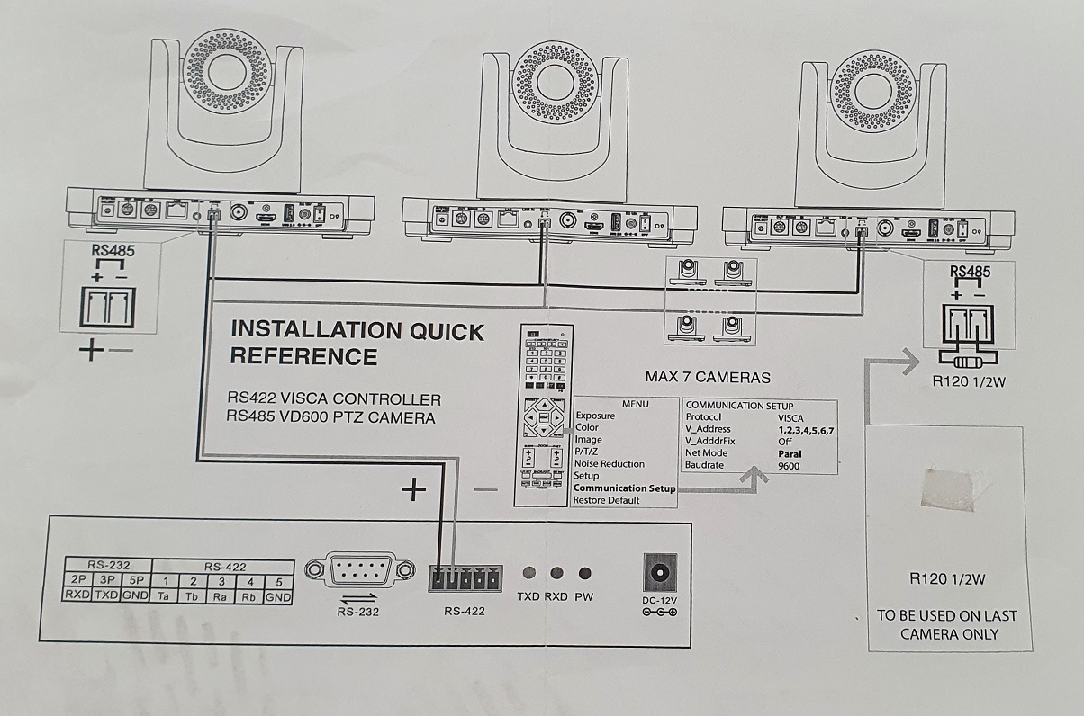
I will attach some photos of the controller and my plan's scheme.
Thanks a lot!
Here is a link that will define the protocol for you. Note the values are in HEX notation. I would start by doing a tutorial or two on RS485 then connect only the receive side and see if you can get the correct data first. Please note baud rate is very important and must be correct. From what I can see it is one way to the camera and does not expect a reply, that would be the video stream.
They show a 120 Ohm resistor on the end of the line, that is important. If you connect before it with a wire less then a meter/yard in length you should be OK. Let us know how you are doing.
If you have not purchased an Arduino I would suggest using a Mega as it has more then one serial port or the new Nano that has two but I have not seen any documentation on how to use it.
@gilshultz@horace
We are using only two cameras. I've put the 120 Ohm resistor on the one that is further away. The wires are connected together right at the controller (not from Cam 1 to Cam 2). Please see the scheme below:
I've just started to learn about this protocol here: What is the difference between RS-232, RS-422, and RS-485? | Optcore because to be honest, I don't understand why in the controller's scheme they made us connect from RS-422 (controller) to RS485 (camera). I would expect both to be the same protocol.
@gilshultz can you please attach the link that you are talking about? Thank you!
I added it again, It showed up here when I posted it but it disappeared. This has happened several times to me, no idea why. You should wire the cameras camera to camera, not back to the source. If it works don't worry about it. The way you are doing it causes reflections. Also the terminator should be on the last camera, only one terminator for the network, the other should already be in the controller.
@3AgL3_DJ If memory serves, then I think your first problem will be that RS-422 isn't a bidirectional bus, like RS-485, with devices that relinquish control of the bus. If your PTZ controller is the transmitter, then I think it will always be driving the Ta and Tb lines which would suggest that you can't add a second transmitter to the Ta and Tb lines.
RS-422 and RS-485 use different voltage levels to exchange data and are not compatible with each other. Are you sure that the information is correct?
Having thought a bit more, were you thinking of completely replacing the PTZ controller with an Arduino / PC solution that simply sent out pre-set "co-ordinates" to each camera to cause them to point at the location of each speaker?
RS-422 and RS-485 use different voltage levels to exchange data and are not compatible with each other. Are you sure that the information is correct?
Well, that's the setup that I see from the manufacturer, we've followed that guide. Check the last photo (Installation quick reference) from post #1. The controller has an RS-422 interface and the cameras have RS485. That's how we've set them up and they work without any issues. Now I'm a bit more confused.
were you thinking of completely replacing the PTZ controller with an Arduino / PC solution that simply sent out pre-set "co-ordinates"
Yes but that's out of the question (at least for now) because there are more groups of people using the system and we can't force them to use our PC and app.
which would suggest that you can't add a second transmitter to the Ta and Tb lines.
Ok, but the protocol doesn't send the signal all the time (eg. while idle), right? There is current over the wires only when data is being sent. If so, the PTZ controller should ignore that data if it's not designed to read it - and if that's an issue, I can just attach a relay to the wires and disconnect the PTZ controller for a few seconds while a write the data to the cameras, like so:
Should this be better?
Also, thank you @gilshultz for the VISCA protocol command list! Extremely useful!
You are welcome. I found this: " To convert the existing RS-422 interface into a RS-485 one, all you have to do is to connect both pairs of receive and transmit line poles by shorts (R+ with T+ and R- with T-) . A simple two wire (differential) communication from one RS-485 master to up to 10 DLS/FLS-C devices can be created on this way." so in your case simply do not connect the Arduino Receiver pins, nothing is expected back as far as I can tell. The RS485 Standard is similar to the RS422 standard upon which it is based . The main difference is that up to 32 transmitter receiver pairs may be present on the line at one time. A 120 Ohm resistor should be used to terminate either end of the main line. I believe the second was from Intersil, there driver is for both. Both busses use two-wire differential signals with identical voltage levels . From a hardware point of view it is possible to connect RS422 and RS485. RS485 is bidirectional, you can share the same bus for drivers and receivers, in 422 you have a driver and many receivers.