Four 5volt relays, when on at the same time, use 4x80mA = 320mA. Plus ~40mA for the Arduino.
12volt - 0.7volt reverse protection diode (if you use the DC jack) = 11.3volt.
Voltage across the regulator is 11.3 - 5 = 6.3volt
Power in the regulator is 6.3 * ~360mA = 2.25watt.
About twice the maximum the power.
The onboard 5volt regulator of the Arduino is probably overheating when two or more relays are active.
A 9volt supply on the DC jack might just be ok.
Next time buy a 12volt relay module and supply the relay coils from the raw 12volt.
Leo..
I tried a new scenario :
Plug only the USB for powering the Arduino
So in this situation the Arduino is powered via USB (on a laptop on battery)
The lights are powered by the wall outlet.
I added some logs, add saw that the relays don't behave randomly but the arduino reboot after 8/10seconds.
Any ideas ?
Here my code :
/* This Arduino program allow to control a traffic light (or three light) thanks to a bluetooth app on your mobile */
/* It contains many possibilities (mods) to enjoy your traffic light */
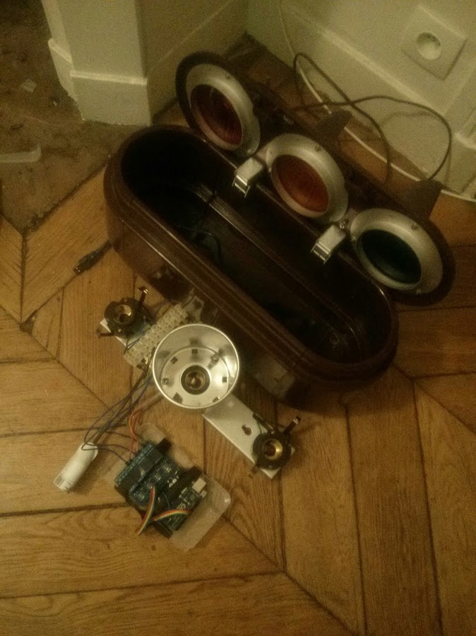
/* I used it with a 4 chanels relay and an Arduino Uno + A Nexus 4 */
/* Author : Quentin HESS */
/* Date of creation : 2015.10.20 */
/* Comments : Still in progress (I'm waiting the bluetooth module for Arduino) */
// define pin heads
int red = 10;
int orange = 9;
int green = 8;
/*
- 0 is red
- 1 is orange
- 2 is green
- 99 is all down
*/
int current_light = 99; // all is down by default
/* time variables in ms, don't touch it */
long lastchange = 0;
/* mod variables
0 is normal (red, green then orange and etc)
1 is outage (orange blinking)
2 is go_carefully (green blinking)
3 is trains_stop (red blinking)
4 is manual (green or red)
5 is full_manual (green, orange, red)
*/
int mod = 99; // no current mod at this point
int newmod = 1; // default mod loaded during setup function
long delay_default = 10000; // delay for green and red
long delay_orange = 3000; // delay for orange
int delay_blink = 600; // delay for blinking
bool status = 0; // just for blinking
long current_delay = delay_default;
/* relays_conf */
bool down = HIGH;
bool up = LOW;
/* Here we are ! */
void setup() {
Serial.begin(9600); // open serial connection
pinMode(red, OUTPUT); // set pin on output
pinMode(orange, OUTPUT); // set pin on output
pinMode(green, OUTPUT); // set pin on output
digitalWrite(green, down);
digitalWrite(orange, down);
digitalWrite(red, down);
Serial.println("reset");
switchmod(newmod); // load the default mod
}
void loop() {
// call function off the current mod
Serial.print(digitalRead(red));
Serial.print(",");
Serial.print(digitalRead(orange));
Serial.print(",");
Serial.print(digitalRead(green));
Serial.println(" ");
delay(1000);
switch (mod) {
case 0:
normal();
break;
case 2:
go_carefully();
break;
case 3:
trains_stop();
break;
case 4:
manual();
break;
case 5:
full_manual();
break;
default:
outage();
break;
}
}
/* function for initializing each mod */
void switchmod(int newmod) {
if(newmod != mod) {
switch(newmod) {
case 0:
digitalWrite(green, down);
digitalWrite(orange, down);
digitalWrite(red, up);
current_light = 0;
break;
case 1:
case 2:
case 3:
switch (current_light) {
case 0:
digitalWrite(red, down);
break;
case 1:
digitalWrite(orange, down);
break;
case 2:
digitalWrite(green, down);
break;
}
break;
}
mod = newmod;
}
}
/* list off mods */
void normal() {
if(millis() > (lastchange + current_delay)) {
lastchange = millis();
current_delay = nextlight();
}
/*Serial.println(lastchange);
Serial.println(current_delay);
Serial.println("===");*/
}
void go_carefully() {
blinklight(2);
}
void trains_stop() {
blinklight(0);
}
void outage() {
blinklight(1);
}
void manual() {
/* WIP */
}
void full_manual() {
/* WIP */
}
/* go to the next light */
int nextlight() {
/* int current_light;
int delay;*/
long delayreturn = 0;
switch (current_light) {
case 0:
digitalWrite(red, down);
digitalWrite(green, up);
delayreturn = delay_default;
current_light = 2;
break;
case 1:
digitalWrite(orange, down);
digitalWrite(red, up);
delayreturn = delay_default;
current_light = 0;
break;
case 2:
digitalWrite(green, down);
digitalWrite(orange, up);
delayreturn = delay_orange;
current_light = 1;
break;
}
return delayreturn;
}
/* blink a light */
void blinklight(int light) {
if(status) {
current_light = light;
}
else {
current_light = 99;
}
Serial.print(status);
Serial.print(",");
Serial.print(millis());
Serial.print(",");
Serial.print(lastchange);
Serial.print(",");
Serial.print(light);
Serial.println(" ");
Serial.println("=======");
if(millis() > (lastchange + delay_blink)) {
lastchange = millis();
status = !status;
switch (light) {
case 0:
digitalWrite(red, status);
break;
case 1:
digitalWrite(orange, status);
break;
case 2:
digitalWrite(green, status);
break;
}
}
}
You can narrow down the cause of the reboot issue by disconnecting the relays from the Arduino and run it. If it still reboots then create a simple program that only sends a message to the serial monitor when setup() runs if it doesn't reboot then you know the issue is with your program.
titux75:
The relays worked perfectly when my Arduino Uno was powered with USB, but when I use the 12V power on it, the relays behave randomly.
Do you have any explanation please ?
Yes, you are picking up direct interference spikes across the 12V rail, probably because you've
taken no precautions to reduce/prevent EMI, and made worse by the fact you have a cheap
12V power supply running from the same mains power circuit you are switching.
You may need lots of extra decoupling on the 12V supply, you should be using twisted pair for
all the power wiring (or at least limiting any loops to the minimum area possible), and running
the switched mains load wiring well away from the Arduino and 12V wires.
wiring
pert:
You can narrow down the cause of the reboot issue by disconnecting the relays from the Arduino and run it. If it still reboots then create a simple program that only sends a message to the serial monitor when setup() runs if it doesn't reboot then you know the issue is with your program.
The problem appear only when I plug the power on the lights (220v) : when it's not, the arduino and the relays (leds on it) work well, so I think the sketch is good.
MarkT:
Yes, you are picking up direct interference spikes across the 12V rail, probably because you've
taken no precautions to reduce/prevent EMI, and made worse by the fact you have a cheap
12V power supply running from the same mains power circuit you are switching.
You may need lots of extra decoupling on the 12V supply, you should be using twisted pair for
all the power wiring (or at least limiting any loops to the minimum area possible), and running
the switched mains load wiring well away from the Arduino and 12V wires.
wiring
I tried to remove the 12v power supply and power the Arduino with the USB instead (with a laptop on battery) and the behaviour was the same.
Here's something you might try, even if it doesn't solve your problem it's good practice for better isolation of the Arduino from the mains. The thing that's never documented by the sellers of these relay modules is that you can remove that blue jumper and connect a separate supply line for the relay coils. So give that a try with a 5v power supply and then your Arduino voltage regulator is only powering the Arduino and the optocouplers.
Yep kind of annoying, all the tutorials I saw don't mention any external power supply for the relays as well, and I didn't find any 5v power supply with Dupont connectors.
What is the best compact way to power it ? (the traffic light case is not that big )
titux75:
I didn't find any 5v power supply with Dupont connectors.
I used to cut female jumper wires and solder splice the wires with shrink tube over them but then I finally bought one of the crimper tools for them and a bunch of the connectors and it's way faster and more professional that way, especially for doing multiple connector cables.
titux75:
What is the best compact way to power it ? (the traffic light case is not that big )
I guess the way to make it the most compact would be to have the power supply separate from the traffic light. If there is space you could mount a barrel jack on the case so that the power supply could be unplugged from it. The downside is it will be more messy externally because it will require multiple wires going into the light instead of just one wire for the mains supply but I don't think it's a big deal.
Yep the plan is plug it like that :
Relay 1,2,3,4 -> Uno 8,9,10,11
Relay VCC -> Uno 5V
Remove the JdVcc/VCC jumper
Relay GND -> Power supply GND
Relay JDVcc -> Power supply Vcc
Yep I found one in my stuffs
I plugged it on je Jdd-Vcc and the ground and no resets anymore, thanks a lot.
I have got two more questions :
1/ I saw many tutorials who said that we should plug the arduino gnd to the relay board gnd even when an external supply is plugged on the relay board and others who said "don't do that". What is the difference ?
2/ I would like to plug a 5v bluetooth module on the same arduino and would like to save the 5v pin; with the relay board powered with an external source, is it possible to use the 3.3v arduino pin instead of the 5v one to send the i/o signal to the RB ?
I think it's a bad idea to connect the ground from the Arduino. The ground is connected to the relay coil power source so if you connect that to the Arduino then you will lose the isolation. It works fine without the grounds connected so there's no good reason to do it The optocouplers are active low so you only need the i/o pin and vcc connected from the Arduino.
As for the 3.3v thing I'm not sure. It seems to work fine for me though it's certainly driving the optocoupler at a much lower current level. It makes sense that they would design the modules to work with either logic level.
titux75:
1/ I saw many tutorials who said that we should plug the arduino gnd to the relay board gnd even when an external supply is plugged on the relay board and others who said "don't do that". What is the difference ?
2/ I would like to plug a 5v bluetooth module on the same arduino and would like to save the 5v pin; with the relay board powered with an external source, is it possible to use the 3.3v arduino pin instead of the 5v one to send the i/o signal to the RB ?
No opto isolation if you join grounds or leave the JD-VCC jumper in.
The opto LEDs are connected between opto VCC and relay inputs.
So a ground connection is not needed to drive the opto LEDs.
No. Don't connect 3.3volt to opto VCC.
Use the 5volt pin.
Don't worry. The current draw per relay opto is very small. ~2mA.
You can drive a module and a shipload of optos from the 5volt rail.
Leo..