I read some wiring instructions and got confused by the supply voltage which should be 3.3V for the SD-card. Therefore it is necessary to use a level shifter in order to use it with a regular 5V Arduino like the Uno. Since there is a onboard voltage divider (aka the crappy low-tech level shifter) there is no need for a level shifter and you can supply it directly to 5V - as said in the item descripton "Support 5V/3.3V input". However some wiring instructions state that you have to supply both voltages 3.3V and 5V for this sd card module (according to the layout). Does anyone have such a module?
It has not arrived yet but I want to etch a pcb to easily implement it into my circuit. Therefore I need to know it beforehand the ebay seller hasn't replied yet
This seems to be the the same design as mine (LC Studio stuff). What do you mean it works bad/not stable? Did you supplied it with 5V and used some resistors to get 3.3V for the sd card?
5V supply is OK. onboard regulator takes care of this.
The 3 other OUT-lines need voltage adjustment. The original solution is NOT very good.
I've experienced that board worked unstable.
The suggested fix can be done - parly using the already ombord 10k resistors
..also: be sure to make pin 10 an output
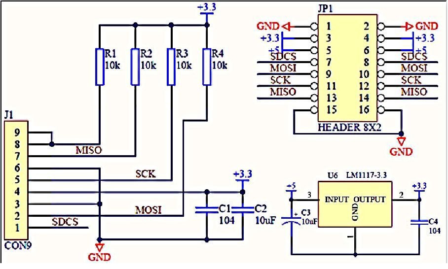
I assume this is the resistor setup of the original design: R1 = 1,8k; R2 = 1k; R3 = 1,8k; R4 = 3,3k; R5 = 2,2k; R6 = 3,3k - so what did you replaced/changed? I took this image as a reference.
And again - do I have to supply both voltages or does it work with either 3.3V or 5V? Just asking because I read instructions stating one has to supply both on that lc studio design
my card matched the design shown.
I'll make a sketch (photo) of my changes.
My original har 4x 10k resistors.
It works reliable with voltage dividers using 4.7k's