This sketch is part of a gear selector for a car that uses a linear actuator to select the appropriate gear for an automatic transmission. The appropriate gear is selected using a dtsp toggle shift – move thru the gear in one direction and back.
Before a gear can be changed, i.e., go from Drive to Reverse etc. the brake switch via the brake pedal must be pushed down. The existing brake switch is normally closed, has 12 volts until the brake pedal is pushed down at which time the voltage goes to 0.
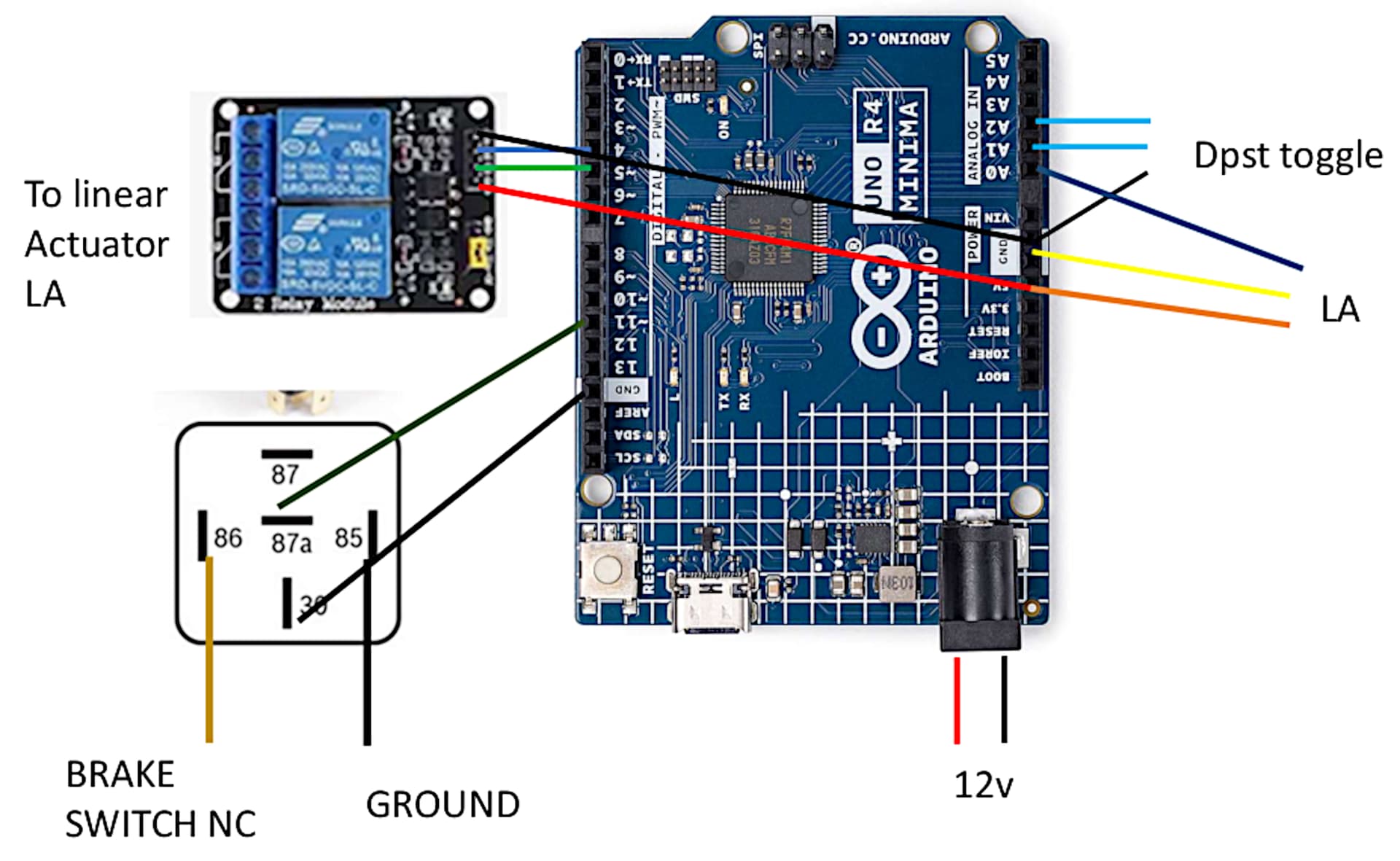
Using a feed from the brake switch, a 5 pin Bosch relay is used as input to the Arduino Uno to signal that the brake switch has gone from 12v to 0v at which time the toggle switch can change gears via the linear actuator.
I have tried numerous iterations of changing the sketch and/or the Bosch wiring to no avail.
Here is my sketch and the wiring diagram, which is really focused on the Bosch relay. Any help would be appreciated. SHIFTER PIC.pdf (362.6 KB)
 #include <ezButton.h>

ezButton button1(A2);
ezButton button2(A1);
#define IN_PIN   4
#define OUT_PIN  5
#define POTENTIOMETER_PIN   A0 // the Arduino pin connected to the potentiometer of the actuator
int swcnt = 0;
int TargetPosition[7] = {77, 152, 202, 250, 302, 342, 382};
#define TOLERANCE  3
const int brksw  = 11;   //switch to make sure brake is pushed
int brkswState = HIGH;

void setup() {
  Serial.begin(9600);
  button1.setDebounceTime(50); // set debounce time to 50 milliseconds
  button2.setDebounceTime(50); // set debounce
  pinMode(IN_PIN, OUTPUT);
  pinMode(OUT_PIN, OUTPUT);
  pinMode(brksw, INPUT_PULLUP);
}
void UPDOWN() {
  button1.loop(); // MUST call the loop() function first
  button2.loop(); // MUST call the loop() function first

  int btn1State = button1.getState();
  int btn2State = button2.getState();
  brkswState = digitalRead(brksw);
  if (button1.isPressed() && brkswState == LOW) {
    swcnt++;
    if (swcnt > 6 ) {
      (swcnt = 6  );
    }
  }
  if (button1.isReleased()) {
    brkswState == HIGH;
  }
  if (button2.isPressed() && brkswState == LOW) {
    swcnt--;
    if (swcnt < 0) {
      (swcnt =
      0 );
    }
  }
  if (button2.isReleased()) {
  brkswState = HIGH;
  }
}
void loop() {
  UPDOWN();
  int stroke_pos = analogRead(POTENTIOMETER_PIN);
  if (stroke_pos < (TargetPosition[swcnt] - TOLERANCE)) {
    digitalWrite(IN_PIN, LOW);
    digitalWrite(OUT_PIN, HIGH);
  }
  else if (stroke_pos > (TargetPosition[swcnt] + TOLERANCE)) {
    digitalWrite(IN_PIN, HIGH);
    digitalWrite(OUT_PIN, LOW);
  }
  else
  {
    digitalWrite(IN_PIN, HIGH);
    digitalWrite(OUT_PIN, HIGH);
  }
  Serial.println(swcnt);
  Serial.print ("position  ");
  Serial.println(stroke_pos);
  Serial.print("target  ");
  Serial.println(TargetPosition[swcnt]);
}
I would you to fry Arduinos, assuming you are connecting the coil pins, 87A and 30 directly to the Arduino. I do not have a clue as to what those numbers are. Your picture is missing a lot a annotated schematic would help a lot.
Yes I know that but what part of the relay do they connect to. I do not feel like spending the time to look it up. I also do not think the OP knows what the electrical system is like. Let me give the OP a hint:
As we know:Arduinos were designed for and are are intended for experimentation and learning, often with breadboards and loose wires that eventually break if vibrated. Most important, the boards are not protected against harsh, dirty or electrically noisy environments found in industrial, automotive and other commercial
applications. It is unreliable as it is not suitable for industrial, automotive and other commercial operation.
The current issue is that if you use the toggle switch to move the actuator it works if the brake is pushed or not. Its like it is disregarding the whole pushing of the brake