Arduino + SimpleFOC smallest footprint

Hi all,
Arduino Newbie here.

I have a project i am working on - a record player, using a BLDC motor to turn the platter. i was kindly provided the utline for the code, by the originator of the project, and made th tweaks necessary for my motor.

in my original setup, i was using an Arduino UNO (Elgoo) and a SimpleFOC mini board to drive the motor. after some tweaking, I got it close to perfect fr my needs, but the SimpleFOC mini could not drive the Arduino, so would need two power supplies.

I purchased a SimpleFOC Shield, and now the whole thing it almost perfect - apart from the size of the boards combined.

So, after some googling, I read that the Arduino Nano should operate like the Uno, and had the idea of splitting the power supply to two buck converters, setting one at 5v and one at 12v for the SimpleFOC.
However, even if I use the USB for power, and the DC power supply (wall plug) to power the SimpleFOC Mini, the motor just vibrates a small amount - barely audible, but you can feel it pulsing. this is the same code as used before I went to the shield, and the same as the one on the full size setup. the code uploads fine (Old Bootloader), but just doesn't seem to want to work.
Am I missing something with the Nano's compatability with what I want to do here?

Please let me know if more info is needed. Or if it's the Nano that is likely to be the issue in this particular setup.

I'm just looking for what I already have, but in a smaller footprint, with a single power supply, if possible. I can work with what I have, but for structural reasons, a smaller board and pricer option would be preferable.

Thanks

Please read and use this link: How to get the best out of this forum - Development Tools / IDE 1.x - Arduino Forum

You missed most everything helpers need to know.

Post an annotated schematic showing exactly what you have. Be sure to include all connections, power, ground, power sources and note any leads over 10"/25cm. Hint: myself and many others probably do NOT have the same parts as you have so a frizzy is not that useful. Also post a clear picture of your setup if you can.

Thanks for the replies.

I'm heading out to work soon, so can't provide those things just yet.

I guess the main crux of my question was "Is there anything different between the Uno and the Nano, which could cause the issue?" Rather than help with any wiring.
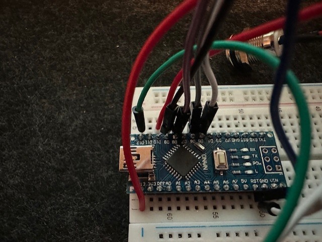
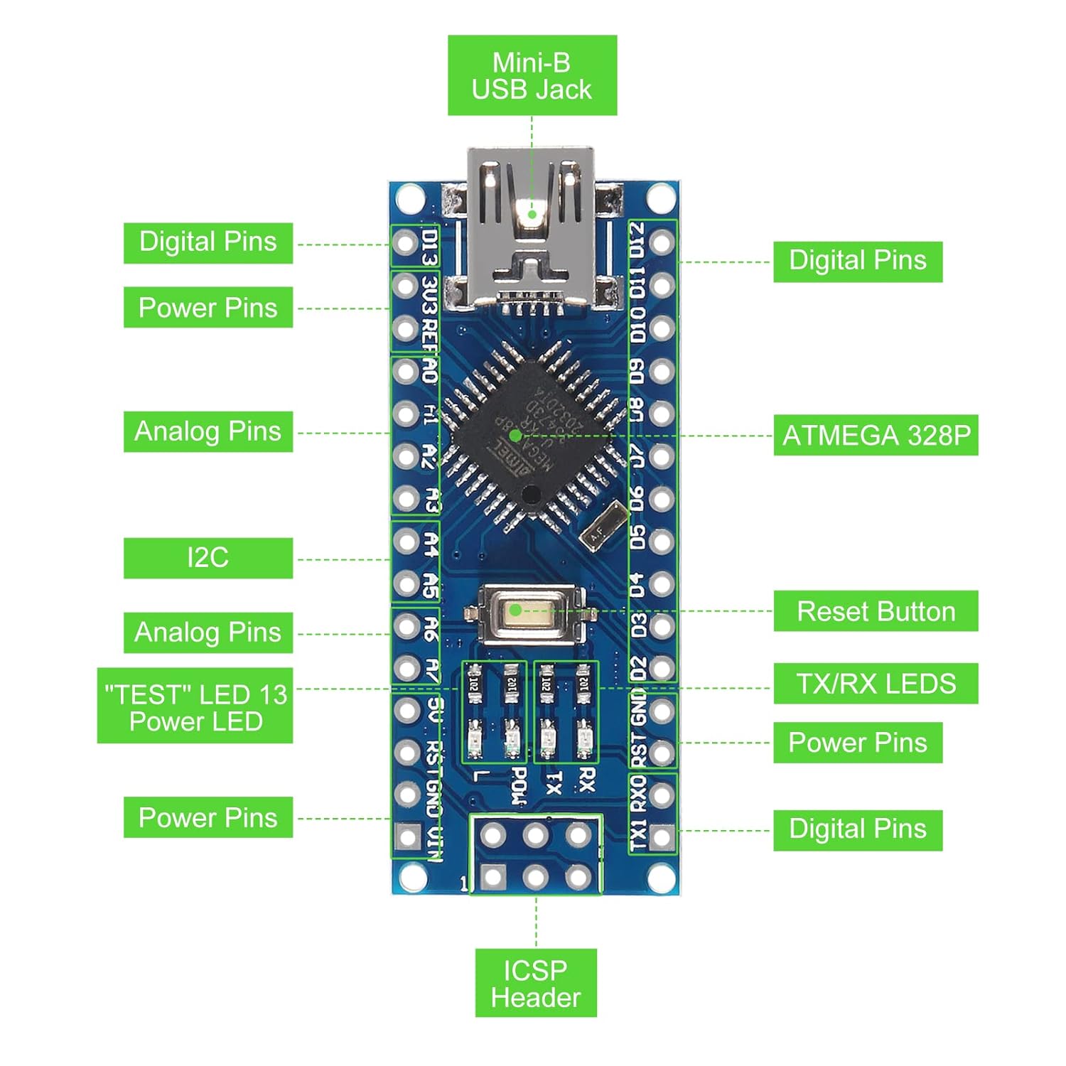
I saw a post about the Nano, mentioning MISO MOSI and SCK pins, but don't know if that means anything for me with this setup. I have a switch wired to 11 and 12, and two momentary buttons wired to 10 and 13.

I'll provide the requested info as soon as I can, but was just wondering if there was something that clashes with these pins.

Quick edit - this is what I can give now:

/// Open loop motor control example
#include <SimpleFOC.h>
bool doonce = 1;
int debouncetime = 10000;

const int BUTTON_PIN = 10;

int input4Pin = 13;
int input3Pin = 12;
int input2Pin = 11;
int input1Pin = 10; 
// this declares each of our buttons and their pins
// make sure that you use the pins your buttons are wired to

// BLDC motor & driver instance
// BLDCMotor motor = BLDCMotor(pole pair number);
BLDCMotor motor = BLDCMotor (11);
// BLDCDriver3PWM driver = BLDCDriver3PWM(pwmA, pwmB, pwmC, Enable(optional));
BLDCDriver3PWM driver = BLDCDriver3PWM(9, 5, 6, 8);

// Stepper motor & driver instance
//StepperMotor motor = StepperMotor(50);
//StepperDriver4PWM driver = StepperDriver4PWM(9, 5, 10, 6,  8);

void setup() {
  pinMode(input4Pin, INPUT_PULLUP);
  pinMode(input3Pin, INPUT_PULLUP);
  pinMode(input2Pin, INPUT_PULLUP);
  pinMode(input1Pin, INPUT_PULLUP); // these lines declare each of the buttons as an input

   // driver config
  // power supply voltage [V]
  driver.voltage_power_supply = 4.448; //12 then 4.4
  // limit the maximal dc voltage the driver can set
  // as a protection measure for the low-resistance motors
  // this value is fixed on startup
  driver.voltage_limit = 12; //12
  driver.init();
  // link the motor and the driver
  motor.linkDriver(&driver);

  // limiting motor current (provided resistance)
  motor.current_limit = 0.058824;   // [Amps was 0.35   0.058824]

  motor.voltage_limit = 1;
 
  // open loop control config
  motor.controller = MotionControlType::velocity_openloop;

  // init motor hardware
  motor.init();

  Serial.begin(115200);
  Serial.println("Motor ready!");
  Serial.println("Set target velocity [rad/s]");
  _delay(1000);

  motor.disable(); // stops motor
}

  void loop() {

     // read the state of the switch/button:
  int buttonState = digitalRead(BUTTON_PIN);

  // print out the button's state 
  Serial.println(buttonState);

 // button on pin 10
  if (digitalRead(10)==LOW) { // high state means on
       motor.disable(); // stops motor
    }
// button on pin 11
  if (digitalRead(11)==LOW) { // high state means on
     motor.move(3.484); // this button sets the speed to 33.3rpm
  }
 
 // button on pin 12
  if (digitalRead(12)==LOW) { // high state means on
     motor.move(4.709); // this button sets the speed to 45rpm 39.071
    }
// button on pin 13
  if (digitalRead(13)==LOW) { // high state means on
     motor.enable(); // starts motor
     doonce = 1;
      delay(debouncetime);
  }

}

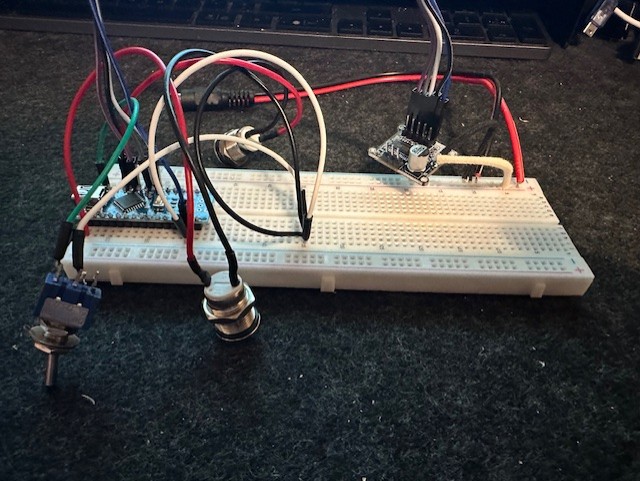
The only thing different from last time (when it worked) is the Nano, where the ground pins are jumpered over to another section for to put thm all on one ground, and I literally just broke off one of the switch wires when taking this pic - so the wire to pin 11 is pissing in the pics.

The driver is a SimpleFOCMini 1.0 (probably clone, but works with the Uno)
Board is a clone Nano (Old Bootloader)

I can provide an attempt at a wiring diagram when I get home later.

Same setup works on the UNO, but not the nano. The Motor just pulses in this setup.

Design wise no, the Nano is the same CPU running at the same voltage. The power supply is different, you can probably draw less current from the 5V. Also, clone Nano's often don't follow the official schematic, but that is usually a CH340 instead of FTDI for USB.

There could be a fault with your Nano, e.g. a pin not soldered correctly.

You are right to concentrate on the differences between your setups, but it is also worth debugging the setup you have got. At least check connections with a meter.

Hi,
Thank you for the reply!

I have tried with 2x Nano's now (came as a pack of two), and they both have the same issue. They do use the CH340, but would that make any difference? i'm assuming my PC has that driver to be able to communicate at all with it(?)

This is the image of the pins listed on the version I purchased from Amazon, with this link


Not sure that says anything different than expected, though.

Everything I can see on the solder joints looks ok, the pin layout matches the first time i set it up (just with a nano rather than Uno), So I'm at a bit of a loss.

At this point, the only other thing I can do, if the rest looks ok, is buy another SimplpeFOC Mini board, and see if THAT's faulty.

Hi all,
I previously had a post about my turntable (record player) Motor setup, with an arduino nano. I was having some issues with the motor not actually moving, and making a cogging-like sound. When I was messing with things, it would occasionally spring into life, but I had no idea why.
When I was just "trying things', I bridged pin 13 and 3v3 on the nano, and it started to work perfectly!

So, Is this a bad thing, or expected, for some reason?

The setup is:

  • Power into 2x Buck converters
  •  1x at 5v into the nano, 1x at 12v into a SimpleFOC mini 
    
  • 2x buttons for motor start, motor stop
  • 1x toggle switch (2 position ON ON) for the speed select - 33.3 and 45rpm

The code is:

/// Open loop motor control example
#include <SimpleFOC.h>
bool doonce = 1;
int debouncetime = 10000;

const int BUTTON_PIN = 10;

int input4Pin = 13;
int input3Pin = 12;
int input2Pin = 11;
int input1Pin = 10; 
// this declares each of our buttons and their pins
// make sure that you use the pins your buttons are wired to

// BLDC motor & driver instance
// BLDCMotor motor = BLDCMotor(pole pair number);
BLDCMotor motor = BLDCMotor (11);
// BLDCDriver3PWM driver = BLDCDriver3PWM(pwmA, pwmB, pwmC, Enable(optional));
BLDCDriver3PWM driver = BLDCDriver3PWM(9, 5, 6, 8);

// Stepper motor & driver instance
//StepperMotor motor = StepperMotor(50);
//StepperDriver4PWM driver = StepperDriver4PWM(9, 5, 10, 6,  8);

void setup() {
  pinMode(input4Pin, INPUT_PULLUP);
  pinMode(input3Pin, INPUT_PULLUP);
  pinMode(input2Pin, INPUT_PULLUP);
  pinMode(input1Pin, INPUT_PULLUP); // these lines declare each of the buttons as an input

   // driver config
  // power supply voltage [V]
  driver.voltage_power_supply = 4.448; //12 then 4.4
  // limit the maximal dc voltage the driver can set
  // as a protection measure for the low-resistance motors
  // this value is fixed on startup
  driver.voltage_limit = 12; //12
  driver.init();
  // link the motor and the driver
  motor.linkDriver(&driver);

  // limiting motor current (provided resistance)
  motor.current_limit = 0.058824;   // [Amps was 0.35   0.058824]

  motor.voltage_limit = 1;
 
  // open loop control config
  motor.controller = MotionControlType::velocity_openloop;

  // init motor hardware
  motor.init();

  Serial.begin(115200);
  Serial.println("Motor ready!");
  Serial.println("Set target velocity [rad/s]");
  _delay(1000);

  motor.disable(); // stops motor
}

  void loop() {

     // read the state of the switch/button:
  int buttonState = digitalRead(BUTTON_PIN);

  // print out the button's state 
  Serial.println(buttonState);

 // button on pin 10
  if (digitalRead(10)==LOW) { // high state means on
       motor.disable(); // stops motor
    }
// button on pin 11
  if (digitalRead(11)==LOW) { // high state means on
     motor.move(3.484); // this button sets the speed to 33.3rpm
  }
 
 // button on pin 12
  if (digitalRead(12)==LOW) { // high state means on
     motor.move(4.709); // this button sets the speed to 45rpm 39.071
    }
// button on pin 13
  if (digitalRead(13)==LOW) { // high state means on
     motor.enable(); // starts motor
     doonce = 1;
      delay(debouncetime);
  }

}

Without Pins 13 and 3v3 connected together, it just cogs (not sure if that's the right term for this particular instance - not turning, just making a noise). Is there something else I have wrong, or is this expected on a Nano?

Post #4 shows a breadboard, but it is now soldered into prototype board. Everything looks correct in terms of the soldering. I just want to try and understand why it works perfectly with those pins connected. I tired both on their own - but they work perfectly when jumped

I'm not an expert, and your breadboard photos are difficult to decipher, but to me, it looks like you have/had no button connected to Pin D13, which is where your code expects a button that will be pushed when you want to run motor.enable().

I don't know what voltage threshold must be crossed for a digital input to be considered to be LOW, but if the voltage supplied by your 3v3 pin is sufficiently low to set the pin state to LOW, then it would cause motor.enable() to be called in each loop.

Conversely, without supplying the D13 pin with a LOW voltage, there will never be a call to motor.enable().

1 Like

Since pin 13 is also tied to the onboard LED and this is a clone, there may be some extra circuitry (or not) associated with that pin. I would move to a different pin.

1 Like

Thank you both for your replies!

I just moved Pin 13 to pin D2, and it worked first time! Thank you!

I have just one more question, though...

When I use the Uno + FOC Shield, it does nothing on initial startup - this is correct. You then Press the start button and the motor turns at the speed set by the toggle switch.

However, on the Nano, when I power on, it starts turning right away. I can stop it by pressing the stop button, and start it again with the start button, but it shouldn't start as soon as it's powered. Do you have any idea what might cause this?

Thanks again!

I have merged your forum topics due to them having too much overlap on the same subject matter @outsidethenine

In the future, please only create one topic for each distinct subject matter and be careful not to cause them to converge into parallel discussions.

The reason is that generating multiple threads on the same subject matter can waste the time of the people trying to help. Someone might spend a lot of time investigating and writing a detailed answer on one topic, without knowing that someone else already did the same in the other topic.

Thanks in advance for your cooperation.

1 Like

Solved it.
Somewhere along the way I had lost motor.disable(); after startup.
Added back in, and now does nothing on startup - as expected.
I changed one of the buttons to a different pin, to see if it was the same kind of thing as the pin 13 situation, but it wasn't. Only explaining as the code below will be different from above.

Very last one for this project. I think I'm using the wrong terminology here, and am sure I need to use something like "while" but...

When the motor is moving, pressing the start button makes the motor stop for a split second and start again. How would I say "while button 2 is HIGH - don't re-run the start motor command."?

The bit I wan't to change:

  if (digitalRead(2)==LOW) { // high state means on
    motor.enable(); // starts motor
    doonce = 1;
    delay(debouncetime);
  }

I feel Like doonce isn't working here(?)

FULL code

#include <SimpleFOC.h>
bool doonce = 1;
int debouncetime = 10000;


const int BUTTON_PIN = 3;


int input3Pin = 12; // - Toggle Position 1 -45 rpm
int input2Pin = 11; // - Toggle Position 2 -33.3 rpm
int input1Pin = 3; // - Stop button
int input4Pin = 2; // - Start button - was previoulsy top
// this declares each of our buttons and their pins
// make sure that you use the pins your buttons are wired to

// BLDCMotor(pole pair number, phase resistance (optional) );
BLDCMotor motor = BLDCMotor(11);
// BLDCDriver3PWM(pwmA, pwmB, pwmC, Enable(optional));
BLDCDriver3PWM driver = BLDCDriver3PWM(9, 5, 6, 8);

// instantiate the commander
Commander command = Commander(Serial);
void doTarget(char* cmd) { command.scalar(&motor.target, cmd); }
void doLimit(char* cmd) { command.scalar(&motor.voltage_limit, cmd); }

void setup() {
  pinMode(input4Pin, INPUT_PULLUP);
  pinMode(input3Pin, INPUT_PULLUP);
  pinMode(input2Pin, INPUT_PULLUP);
  pinMode(input1Pin, INPUT_PULLUP); // these lines declare each of the buttons as an input


  // use monitoring with serial 
  Serial.begin(57600);
  // enable more verbose output for debugging
  // comment out if not needed
  SimpleFOCDebug::enable(&Serial);

  // driver config
  // power supply voltage [V]
  driver.voltage_power_supply = 12;
  // limit the maximal dc voltage the driver can set
  // as a protection measure for the low-resistance motors
  // this value is fixed on startup
  driver.voltage_limit = 6;
  if(!driver.init()){
    Serial.println("Driver init failed!");
    return;
  }
  // link the motor and the driver
  motor.linkDriver(&driver);

  // limiting motor movements
  // limit the voltage to be set to the motor
  // start very low for high resistance motors
  // current = voltage / resistance, so try to be well under 1Amp
  motor.voltage_limit = 12;   // [V]
 
  // open loop control config
  motor.controller = MotionControlType::velocity_openloop;

  // init motor hardware
  if(!motor.init()){
    Serial.println("Motor init failed!");
    return;
  }

  // set the target velocity [rad/s]
  //motor.target = 3.48; // 33.3RPM
  //motor.target = 4.71; // 45RPM

  // add target command T
  command.add('T', doTarget, "target velocity");
  command.add('L', doLimit, "voltage limit");

   Serial.println("Motor ready!");
  Serial.println("Set target velocity [rad/s]");
  _delay(1000);

  motor.disable(); // stops motor
  
}


void loop() {


       // read the state of the switch/button:
  int buttonState = digitalRead(BUTTON_PIN);

  // print out the button's state 
  Serial.println(buttonState);

 // button on pin 3
  if (digitalRead(3)==LOW) { // high state means on
       motor.disable(); // stops motor
    }
// button on pin 11
  if (digitalRead(11)==LOW) { // high state means on
     motor.move(3.484); // this button sets the speed to 33.3rpm
  }
 
 // button on pin 12
  if (digitalRead(12)==LOW) { // high state means on
     motor.move(4.709); // this button sets the speed to 45rpm
    }
// button on pin 2
  if (digitalRead(2)==LOW) { // high state means on
    motor.enable(); // starts motor
    doonce = 1;
    delay(debouncetime);
  }


}

You need to detect when your button gets pressed, not if your button is pressed. Look at the State Change Detection example in the IDE for how to code it up (File->examples->02.digital->State Change Detection)

1 Like

Will do - thanks!

ok, I think I have the same question, but based on a different function.

If I set up the whole function to check the last button state, to be able to reference it - how do I say "Just carry on??"
So if the motor is already turning (button 2 pressed last ), and you press button 2 again - just keep going - Don't restart the action associated with the start function.
Everything I am reading is to DO something if the state has changed. I just want the motor to keep turning as-is.

Just keep track of what state you are in. In the simplest of terms, you have a new global variable

bool isMotorRunning;

Initially it is false. When you detect a button state change, go through the logic

if ( lastButtonState != currentButtonState ) {
// button has changed
  if ( currentButtonState == LOW ) {
    // button has been pressed
    if ( isMotorRunning == false ) {
      // turn motor on here
      ...
      isMotorRunning = true;
    }
    else {
      // motor already running, do nothing
    }
  }
  else {
    // button has been released
    // do whatever need being done
  }
}
...

Thanks for taking the time to explain that! I didn't know you could just say else{} and nothing would change.
Will try this later, after work. :+1:

Typically, rather than having an empty else clause, you just don't have it at all. I put it there for clarity.

Yeah I think I'm a bit too new to this to start trying to piece together bits of code. I think I need a lot more practice at what does what.
I've tied adding in some of the bits for the example code on recording botton states, and adding in the missing bits from what you posted above, but it didn't work. the motor starts right away again, then stops when the stop button is pressed, but doesn't restart.
i know it will be simple for you to understand, but i'm extrememly new to this, so i think i'm just trying to get ahead of myself a little. Need to spend some time with the examples and understanding the syntax.
I appreciate your help, though!

We all started at some point. If you post your code, people can help. If you don't, you're on your own. People are usually very willing to help folks along who are trying...