Hello,
I have completed an Arduino tachometer project entirely based on another project posted here: Reading an Engine’s RPM with Arduino
Thanks for that great post @ [feynman137]!
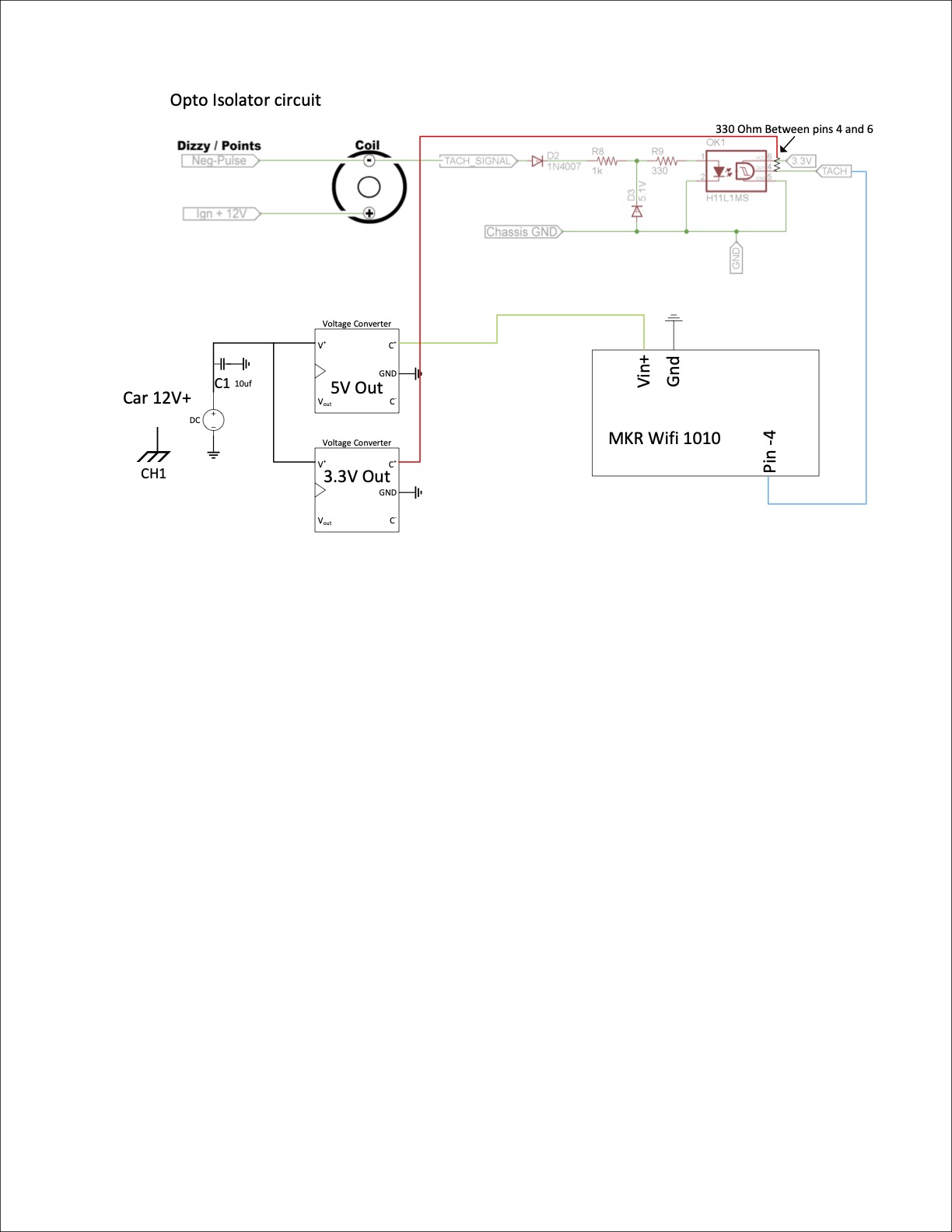
I am using an MKR WiFi1010 and have tested my circuit on the bench even going as far as buying the same signal generator and all works as it should, including having a perfect square wave at 3.3V output of the isolator circuit with a 12V input.
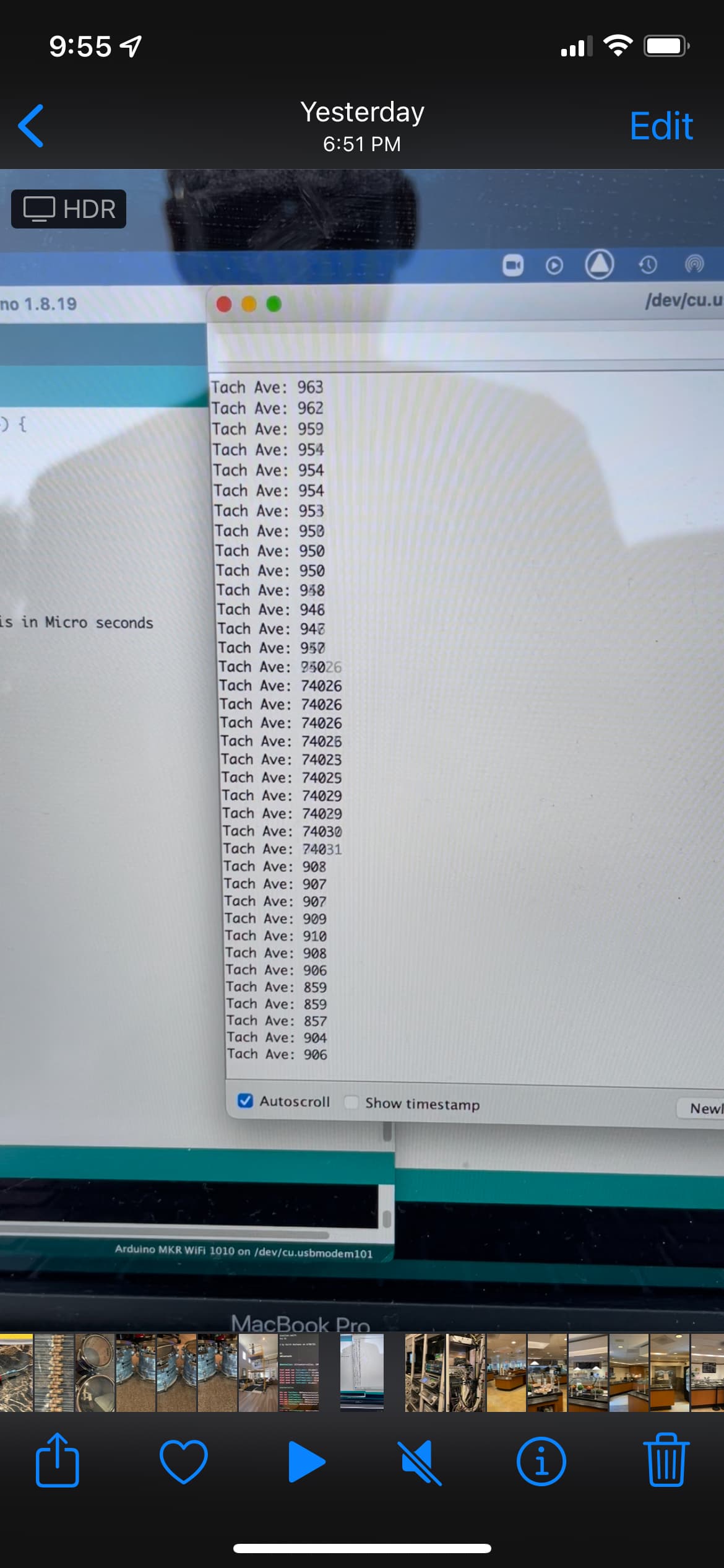
The issue I have though is that when wired to the car which is a VW bug with a stock 1600 DP engine with a Bosch Blue coil and a 009 distributer, I get good readings and a lot of off the charts readings. Doesn't matter what RPM I'm at and I have tried different grounding schemes but nothing seems to make it solid. I have also measured the voltage and frequencies coming off the NEG side of the coil and while they both do slew around a bit it certainly isn't anything that result in those number readings that are off the chart.
So I'm wondering if this has something to do with my circuit, code or installation or is it actually the car itself. Could the problem be that the output of the coil is averaging at around 8-10 Volts instead of 12V so the really high numbers are actually missed triggers? Bad grounding? I'm out of ideas.
Thanks for any input.
int highTime;    //integer for storing high time
int lowTime;     //integer for storing low time
float period;    // integer for storing period
float freq;      //storing frequency
float RPM;       //storing RPM


void setup()
{
  Serial.begin(9600);
  pinMode(4,INPUT);  //Setting pin as input

}

void loop()
{
    highTime=pulseIn(4,HIGH);  //read high time
    lowTime=pulseIn(4,LOW);    //read low time
    period = highTime+lowTime; // Period = Ton + Toff
    freq=1000000/period;       //getting frequency with totalTime is in Micro seconds
    RPM = (freq/2)*60;
    Serial.print(  "RPM:  ");
    Serial.println(RPM);
    delay(100);


}
Please bring up at least pen and paper and make schematics. Your lab is impressive. Thanks for the pics.
More than 30 years ago I tapped the spike at the ignition coil low side and used as the base for RPM, and even the speed of the car! It worked perfectly during 10 years, until I sold the car.
No actually.. just used the meter to check voltage and frequency. Never done that with an O scope. Just literally go to chassis ground and coil Neg terminal?
You have almost world class equipment (although somewhat old). It does baffle me why you wouldn't use it to answer the specific questions you have. Go wherever you want to go to get a useful reading - so long as the voltage is not too high.
8 ~ 10V is normal, when cranking, the coil is fed directly from the batt for max spark voltage, when running, the current is limited through a resistor (usually switched by the starter solenoid) so coil doesn't overheat.
Do you get clean pulses with the circuit in the car?
If I was me, I would use external interrupt for pulse detection.
I do get clean pulses out of the circuit feeding into the Arduino. Even when I see the abnormal values in the serial monitor the scope is still looks good.
Chances are, if all you have so far is a breadboard assembly, arrays of loose wiring, all balancing on the fan housing and held in place with duct tape, it would be picking up all sorts of high tension ignition noise.
Ha! Its not quite as bad as duct tape but I do think that is reasonable. The ultimate goal is to make a PCB and wires as short as possible but I wanted to have a working test first. Maybe shielded wire? Solder up the components and retry..
pulseIn returns an unsigned long. Anyways, unsigned long should be used for timing variables.
Maybe try this ...
unsigned long highTime;    //unsigned long for storing high time
unsigned long lowTime;     //unsigned long for storing low time
float period, lastPeriod;  //float for storing period and last period
float freq;                //float for storing frequency
float RPM;                 //float for storing RPM

void setup() {
  Serial.begin(9600);
  pinMode(4, INPUT); //Setting pin as input
}

void loop() {
  highTime = pulseIn(4, HIGH);            //read high time
  lowTime = pulseIn(4, LOW);              //read low time
  period = highTime + lowTime;            //Period = Ton + Toff
  if (period < 1000) period = lastPeriod; //error: freq > 1000, RPM > 30,000, therefore use last period
  else lastPeriod = period;
  freq = 1000000.0 / period;              //getting frequency with totalTime is in Micro seconds
  RPM = (freq / 2.0) * 60.0;
  Serial.print(  "RPM:  ");
  Serial.println(RPM);
  delay(100);
}