Arduino to Valve Controller not Communicating (RS485)

Hey everyone! I could use some help getting communication between a Controller (Danfoss EKE 1C) and Arduino Mega. Thanks for your feedback!

Purpose: Query/write to controller in a hex-array format using Modbus RS485.

Desired: When the hex message is sent to the controller (slave), the message reply is an echo of the original message to acknowledge (or some exception).

Actual: Every row of buffer reads 0xFF. available() function returns 0 and read() function returns -1.

Troubleshooting:
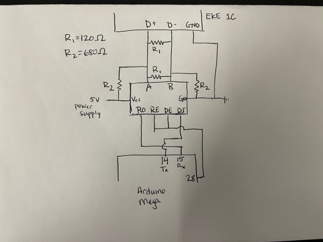
I measured voltages and resistances throughout the circuit. Also verified pins are wired per diagram below.

I attempted to use write() and read() directly using parity and crc calculations that I found online, with the exact same outcome.

I believe the issue may lie in the start/stop/parity bits and the doubled/inverted format in gammon's library, but:

  1. I would expect some response from the controller.
  2. I'm not sure how to build the message (adding start/stop/parity/crc).

Components:
Max485 dev board (Amazon)
Expansion valve controller (Danfoss EKE 1C)
Arduino Mega 2560

My code is a modified version of this Gammon example using the RS485_protocol library.

Arduino Code:

#include "RS485_protocol.h"
#include <SoftwareSerial.h>

const byte ENABLE_PIN = 28;
// const byte LED_PIN = 13;

SoftwareSerial exp_v (15, 14);  // receive pin, transmit pin

// callback routines
  
void fWrite (const byte what)
  {
  exp_v.write (what);  
  }
  
int fAvailable ()
  {
  return exp_v.available ();  
  }

int fRead ()
  {
  return exp_v.read ();  
  }


void setup()
{
  exp_v.begin (19200);
  pinMode (ENABLE_PIN, OUTPUT);  // driver output enable

  Serial.begin (19200);
  Serial.println("Expansion Valve Comms");
}  // end of setup
  
byte old_level = 0;

void loop()
{
  // Wait for user input to start
  while(Serial.available() == 0){
    // do nothing
  }
  
  Serial.println("Querying EV");

  // assemble message per guide step 1: Main switch= off
  byte msg [] = {
    0xF0, // Unit address: 240
    0x06, // Function code (03: read, 06: write)
    0x0B, /* Hi Byte address (PNU) Main switch (PNU: 3001, actual 
        request is for 3000), 00 should be used for 2 digit hex */
    0xB8, // Lo Byte address (PNU)
    0x00, // Desired Value set to off (=0)
    0x00  // Desired Value set to off
  };

  // send to slave  
  Serial.println("Sending Query");
  digitalWrite (ENABLE_PIN, HIGH);  // enable sending
  sendMsg (fWrite, msg, sizeof msg);
  // delayMicroseconds(520);
  digitalWrite (ENABLE_PIN, LOW);  // disable sending


  // receive response  
  byte buf [11];
  byte received = recvMsg (fAvailable, fRead, buf, sizeof buf);
  
  // print response to Serial monitor
  if(received == 0){
    Serial.println("No comms");
  }
  else {
    Serial.println("Message:");
    for(byte i=0; i < sizeof buf; i++){
      Serial.print(buf[i]);
      Serial.print(" ");
    }

    Serial.println(" ---End of Message---");
  }

  // clear serial cache
  while(Serial.available() > 0){
    Serial.read();
  }

}  // end of loop

The breadboard wiring is pretty messy, but here's a diagram:
IMG_3728

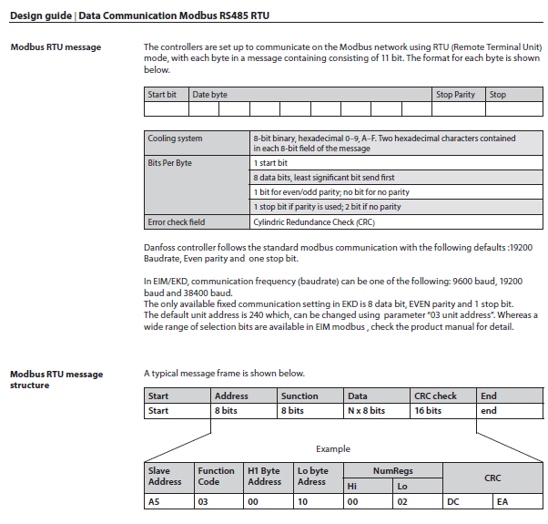
The valve controller provides the following guidance for RS485 communication.

The Mega Serial interfaces operate at TTL voltage levels but different voltage levels are used by RS485

Does the hardware between the Mega and the controller adjust the voltage levels in each direction ?

According to this datasheet the Driver Output (A, B) is 1.5 - 5V and Driver Common-Mode Output of 3V max. Not sure which is the relevant spec. The amazon supplier does not provide any relevant specifications.

@sprusr
The RS485 modules you purchased already have a 120 ohm termination. So remove the one you have next to the module

@sprusr
You also need to connect the RS485 module GND to the Arduino GND

Arduino GND originally shared a rail with the RS485 module and valve controller ground, but the Arduino ground wire started melting. I assumed it was a short.

Should they all go to common ground?

The Arduino GND need to be connected to the RS485 module GND or it wont work. The module GND also needs to be connected to the Controller ground. However, what is the controller ground? What is RGND?

If wires are melting when you connect all the grounds, then you will need to buy an isolated RS485 module.

The controller RS485 port has 3 pins (D+, D-, and GND). I don't have an Rgnd.

The controller is also supplied 24 VDC, but that is grounded separately.

So true, it is marked R7 as far as i know, but you should be able to measure the 120R and verify that it is connecting the A & B lines (pin 6 & 7 respectively on the MAX485 chip. And unless it is going to be a 2 way street it should only have one at one end.

Not bad !, still remove 2x R2 . and remove GND between EKE 1C and the module.
Then connect GND between the module and the Mega. Drop the 5v PSU and draw 5v from the Mega.

It is a Mega which has 4 hwUARTs, you should not use swSerial but one of the hwSerial ports (1, 2 or 3) to connect to the RS485 module.

No it doesn't have to. a general misconception that i have shared for some time but which was pointed out to me some time back. the RS485 does not require common GND between it's modules. Signal is transferred with opposing polarity of the A & B line and is received by measuring the polarity between those lines. GND is not required. Usually common GND does not create any issues, but it may cause a GND loop, and if there is a PSU failure in one of the connected devices this may spread to other devices.

That is never good. Let's hope not to much else has been damaged.

One of the GND's from either the module (/Mega) or the EKE C1 can be used to shield the cable (optional)

According to the specification it requires a ground. Are you saying the spec is wrong?

Even though they've watered down the discussion, it's still there in the 2021 version.
Section 11 here:

And this, from 2013, Section 9, here:

No further discussion warranted.

Do you have any sugestions that will help @sprusr solve his problem?

Show me the link to the specification that you are referring to, don't just blab it out there.

Try google eia/tia rs485

@sprusr Before continuing the struggle with your Arduino, resolve why your ground melted. That's likely to be most important to figure out.

@Deva_Rishi Post#11 should get you started. But we've locked horns on this before, and not agreed, so that's likely to continue.

You always need two.

1 Like

My code is a modified version of this Gammon example using the RS485_protocol library.

I'm curious what has been modified in the Gammon code, as well. Perhaps that should be posted here for inspection.
If the OP has a 'scope, verify that the Enable signal is holding up long enough for the last character to be sent completely. I see there's a delay that's been commented out - why?

Also, from the Gammon page referenced,

I'm not very happy with hard-coded delays. Too low and it is still too quick, too high and the slave is responding before you turn the transmitter off. The exact value has to be carefully tuned, and depends very much on the baud rate in use. The value required appears to be appromately two character times. So for 28800 baud, one character time is 1/2880 which is 347 uS. Doubling that gives about 690 uS.

So it's quite clear he's aware that it's all to easy to turn off the enable before serial transmission is complete. Additionally, it's not clear to me that the simple delay after sending a random-length message is adequate, as when the enable should be changed is going to be dependent upon how many characters have been buffered to send. Putting two chars in the buffer, vs 6(as the OP does) should require a different turn around delay; that's why other RS485 libraries typically do it at a lower level (I think it's based on a delay when the buffer has emptied, but it's a long while since I looked). How one does that with Soft-serial is worthy of investigation.

Would it ideally be done with the tx-FIFO empty interrupt + transmitted bit length ? Or even by sending a dummy byte and responding to the interrupt ?