Arduino development boards always help us to build a project easily and make it look more attractive. Programming an LCD with touch functionality may sound like a complicated task, but it can be made very easy by using Arduino libraries and extension modules. In this project, we will use a 3.5" Arduino TFT LCD to build an Arduino touchscreen calculator that can perform all basic calculations such as addition, subtraction, division, and multiplication.
Materials needed
-
3.5" TFT LCD module
-
9V battery.
Understanding the TFT LCD LCD module
Before we dive into the project, it is important to understand how this 3.5" TFT LCD module works and the model number used. Let's take a look at the pinout of this 3.5" TFT LCD module.
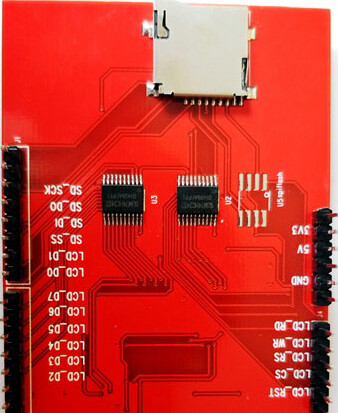
As you can see, the module has 28 pins and fits perfectly into any Arduino Uno / Arduino Mega development board. The table below gives a description of these pins.

As you can see, the module pins can be divided into four main categories, namely LCD command pins, LCD data pins, SD card pins and power pins, we don't need to know the details of how these pins work because they will be implemented by the Arduino library.
You can also find an SD card slot on the bottom of the module shown above. This slot can be used to load an SD card with bmp image files, which can be displayed on our TFT LCD screen using the Arduino program.
Another important thing to keep in mind is your interface IC. there are many types of TFT modules on the market from Adafruit TFT LCD modules to cheap Chinese clones. A program that fits an Adafruit expansion board may not be the same for a Chinese expansion board. Therefore, it is very important to know which type of LCD LCD you are holding. This detail must be obtained from the supplier. If you have a cheap clone like mine, then it most likely uses driver IC ili9341. You can follow the official Arduino tutorial to try some basic example programs to get familiar with this LCD.
Calibrating the touch screen of a TFT LCD
If you intend to use the touch screen function of a TFT LCD module, it must be calibrated to work properly. An LCD screen that is not calibrated is unlikely to work properly; for example, you may touch in one place and the TFT may think it is touching somewhere else. These calibration results are not the same for all boards, so you will have to do this work yourself.
The best way to calibrate is to use a calibration sample program (with a library) or use a serial monitor to detect your errors. But for this project, calibration should not be a big issue due to the large size of the buttons, and I will also explain how to calibrate your LCD in the programming section below.
Connection of Arduino Development Board to TFT LCD
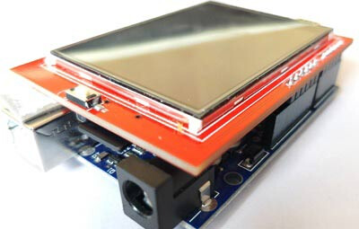
The 3.5" TFT LCD is a great Arduino expansion board. You can push the LCD directly onto the top of the Arduino Uno and have it match the pins perfectly and slide them in. However, for safety reasons, the programming terminals of the Arduino UNO must use small insulating tape in case the terminals come into contact with your TFT LCD screen. the LCD assembled to the UNO development board looks like the following.
Programming the Arduino Development Board
We use the SPFD5408 library to ensure that the arduino calculator code works properly. This is a modified Adafruit library that works seamlessly with our LCD TFT module. You can view the full program at the end of this article.
Note: It is very important to install this library in the Arduino IDE or this program and compile it without any errors.
To install this library, you can simply click on the link above which will redirect you to a Github page. Click on Clone or Download and select "Download ZIP". A zip file will be downloaded.
Now, open the Arduino IDE and select Sketch -> Include Librarey -> Add .ZIP library. a browser window will open to navigate to the ZIP file and click "OK". If successful, you should notice "Library added to your Libraries" in the bottom left corner of your Arduino.
Now you can use the following code in the Arduino IDE and upload it to Arduino UNO to get the touchscreen calculator working. Further down the page, I'll explain the code in small segments.
We need three libraries to make this program work properly. All three libraries are available for download in ZIP file format from the link provided above. I have simply included them in the code as shown below.
#include <SPFD5408_Adafruit_GFX.h>    // Core graphics library
#include <SPFD5408_Adafruit_TFTLCD.h> // Hardware-specific library
#include <SPFD5408_TouchScreen.h>
As mentioned before, we need to calibrate the LCD to make it work properly, but don't worry the values given here are almost universal. The variables TS_MINX, TS_MINY, TS_MAXX and TS_MAXY determine the calibration of the screen. If you feel that the calibration is not ideal, you can make a slight change.
#define TS_MINX 125
#define TS_MINY 85
#define TS_MAXX 965
#define TS_MAXY 905
As we know, TFT LCD screens can display many colors, all of which must be entered as hexadecimal values. To make it more readable, we assign these values to a variable as shown below.
#define WHITE   0x0000 //Black->White
#define YELLOW    0x001F //Blue->Yellow
#define CYAN     0xF800 //Red->Cyan
#define PINK   0x07E0 //Green-> Pink
#define RED    0x07FF //Cyan -> Red
#define GREEN 0xF81F //Pink -> Green
#define BLUE  0xFFE0 //Yellow->Blue
#define BLACK   0xFFFF //White-> Black
Okay, now we can move on to the programming part. This program involves three parts. One is to create a user interface for the calculator using buttons and displays. Then, detect the buttons based on user touch and finally calculate the results and display them. Let's go through them one by one.
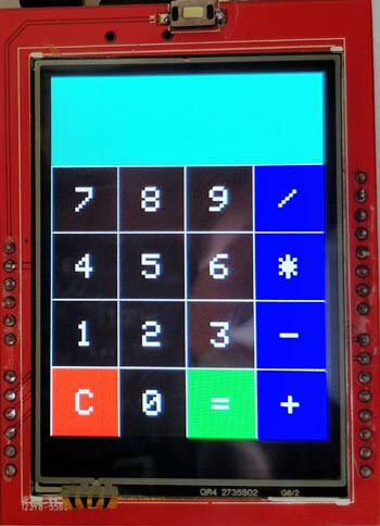
1. Creating the calculator's user interface.
Here you can get creative to design the user interface of the calculator. I simply made the basic layout of the calculator with 16 buttons and a display unit. You must build the design as if you were drawing something on an MS drawing board. The added libraries will allow you to draw lines, rectangles, circles, characters, strings and more in any of the preferred colors. You can learn about the available features from this article.
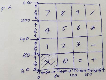
I have used line and box drawing to design a user interface very similar to that of a 90's calculator. Each box is 60 pixels wide and tall.
//Draw the Result Box
  tft.fillRect(0, 0, 240, 80, CYAN);

//Draw First Column
  tft.fillRect  (0,260,60,60,RED);
  tft.fillRect  (0,200,60,60,BLACK);
  tft.fillRect  (0,140,60,60,BLACK);
  tft.fillRect  (0,80,60,60,BLACK);

//Draw Third Column
  tft.fillRect  (120,260,60,60,GREEN);
  tft.fillRect  (120,200,60,60,BLACK);
  tft.fillRect  (120,140,60,60,BLACK);
  tft.fillRect  (120,80,60,60,BLACK);

  //Draw Secound & Fourth Column
  for (int b=260; b>=80; b-=60)
{ tft.fillRect  (180,b,60,60,BLUE);
   tft.fillRect  (60,b,60,60,BLACK);}

  //Draw Horizontal Lines
  for (int h=80; h<=320; h+=60)
  tft.drawFastHLine(0, h, 240, WHITE);

  //Draw Vertical Lines
  for (int v=0; v<=240; v+=60)
  tft.drawFastVLine(v, 80, 240, WHITE);

  //Display keypad lables
  for (int j=0;j<4;j++) {
    for (int i=0;i<4;i++) {
      tft.setCursor(22 + (60*i), 100 + (60*j));
      tft.setTextSize(3);
      tft.setTextColor(WHITE);
      tft.println(symbol[j][i]);
2. Detecting buttons
Another challenging task is to detect the user's touch. Every time the user touches something, we are able to know the X and Y position of the pixel he touched. This value can be displayed on the serial monitor using println, as shown below.
TSPoint p = waitTouch();

X = p.y; Y = p.x;

Serial.print(X); Serial.print(','); Serial.println(Y);// + " " + Y);
Since we designed the boxes with a width and height of 60 pixels and have four rows and columns starting from (0,0). The position of each box can be predicted as shown in the figure below.
In practice, however, this is not the result. Due to calibration issues, there can be significant differences between the expected and actual values.
So, to predict the exact position of the box, you have to click on the line and check its corresponding position on the serial monitor. This may not be the most professional way, but it still works fine. I measured the position of all the lines and got the following values.
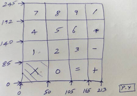
Now, since we know the positions of all the boxes. When the user touches anywhere, we can predict the position he touches by comparing his (X, Y) value with the value of each box, as follows.
if (X<105 && X>50) //Detecting Buttons on Column 2
  {
    if (Y>0 && Y<85)
    {Serial.println ("Button 0"); //Button 0 is Pressed
    if (Number==0)
    Number=0;
    else
    Number = (Number*10) + 0; //Pressed twice
    }


     if (Y>85 && Y<140)
    {Serial.println ("Button 2");
     if (Number==0)
    Number=2;
    else
    Number = (Number*10) + 2; //Pressed twice
}
3. Display the numbers and calculate the results
The final step is to calculate the results and display them on the TFT LCD screen. The arduino calculator can only perform two numeric operations. These two numbers are named as variables "Num1" and "Num2". The variable "Number" is given and taken from Num1 and Num2, and the result is obtained.
When the user presses a button, a number is added to the number. When another button is pressed, the previous number is multiplied by 10 and the new number is added to it. For example, if we press 8, then 5, then 7. then first the variable will hold 8 then (8 * 10) + 5 = 85 then (85 * 10) + 7 = 857. finally, the variable gets the value 857.
if (Y>192 && Y<245)
    {Serial.println ("Button 8");
     if (Number==0)
    Number=8;
    else
    Number = (Number*10) + 8; //Pressed again
}
When we perform any operation, such as addition, when the user presses the Plus button, the value from Number will be transferred to Num1, and then Number will be set to zero so that it is ready to receive the second number as input.
When Equal is pressed, the value from Number will be sent to Num2 and then the corresponding calculation will be performed (in this case addition) and the result will be stored again in the variable "Number".
Finally, this value will be displayed on the LCD screen.
Working Process
The process of working with this Arduino touch screen calculator is very simple. You need to upload the following code to the Arduino development board and then power it up. At this point, a calculator will be displayed on the LCD screen.

You can now enter any number and perform calculations. This is now limited to two operands and one operator. However, you can adjust the code so that there are more options.
After performing the calculation, you must press the "C" key to clear the value on the screen. I hope you understand this project and enjoy creating something similar. If you have any questions, please feel free to post them in the forum or below this post.