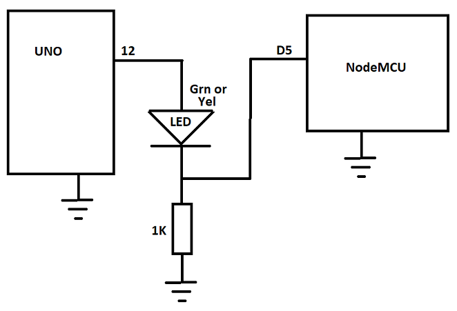
I am trying to interface an arduino uno and a nodemcu and I am having issues. Essentially, I have a sensor that outputs an analog voltage. The Uno reads the analog voltage, and if it is high enough, it sets pin 12 to HIGH. Pin 12 is then connected to D5 of the NodeMCU. The nodeMCU then reads if D5 is high or low, and if it is high, it sends a message to a telegram bot through wifi. However, the NodeMCU constantly reads high from the pin, even if pin 12 is low. I also tried using a voltage divider from pin 12 of the uno to pin D5 of the nodemcu to level shift from 5V to 3.3V but that did not work either. I do not want to have to use serial communication because I am using the SDA and SCL pins to use an OLED screen. Is there any reason that the nodeMCU constantly reads HIGH from pin D5? I thought it would be less of an issue since it's essentially just reading a 1 or 0 but I guess that is not the case. I have attached a diagram and my codes below. Any help is greatly appreciated!

Arduino Code:
#include <Wire.h>
#include <Adafruit_GFX.h>
#include <Adafruit_SSD1306.h>

#define SCREEN_WIDTH 128 // OLED display width, in pixels
#define SCREEN_HEIGHT 64 // OLED display height, in pixels

// Declaration for an SSD1306 display connected to I2C (SDA, SCL pins)
Adafruit_SSD1306 display(SCREEN_WIDTH, SCREEN_HEIGHT, &Wire, -1);

int sensormode = 0;
float voltagelimit = 0.99;
const int buttonPin = 2;

void setup() {
  // initialize serial communication at 9600 bits per second:
  Serial.begin(9600);
  pinMode(12, OUTPUT);
  pinMode(buttonPin, INPUT);

  if(!display.begin(SSD1306_SWITCHCAPVCC, 0x3C)) { // Address 0x3D for 128x64
    Serial.println(F("SSD1306 allocation failed"));
    for(;;);
  }
  delay(2000);
  display.clearDisplay();

  display.setTextSize(1);
  display.setTextColor(WHITE);
  display.setCursor(0, 10);
  // Display static text
  display.println("test");
  display.display();
}

// the loop routine runs over and over again forever:
void loop() {
  // read the input on analog pin 0:
  int sensorValue = analogRead(A0);
  // Convert the analog reading (which goes from 0 - 1023) to a voltage (0 - 5V):
  float voltage = sensorValue * (5.0 / 1023.0);
  // print out the value you read:
  Serial.println(voltage);

  if(sensormode == 0 && digitalRead(buttonPin)==HIGH)
  {
    sensormode = 1;
    voltagelimit = 1.5;
    display.clearDisplay();
    display.setTextSize(1);
    display.setTextColor(WHITE);
    display.setCursor(0, 10);
    display.println("Sensor Range: 2 foot");
    display.display();
  }

  if(sensormode == 1 && digitalRead(buttonPin)==HIGH)
  {
    sensormode = 2;
    voltagelimit = 2.2;
    display.clearDisplay();
    display.setTextSize(1);
    display.setTextColor(WHITE);
    display.setCursor(0, 10);
    display.println("Sensor Range: 1 foot");
    display.display();
  }

  if(sensormode == 2 && digitalRead(buttonPin)==HIGH)
  {
    sensormode = 0;
    voltagelimit = 0.99;
    display.clearDisplay();
    display.setTextSize(1);
    display.setTextColor(WHITE);
    display.setCursor(0, 10);
    display.println("Sensor Range: 3 foot");
    display.display();
  }


   if(voltage > voltagelimit)      //Check the sensor output
  {
    digitalWrite(12, HIGH);   // set the LED on
  }
  else
  {
    digitalWrite(12, LOW);    // set the LED off
  }
  delay(10);
}
NodeMCU code:
#include <ESP8266WiFi.h>
#include <WiFiClientSecure.h>
#include <UniversalTelegramBot.h>
#include <ArduinoJson.h>

// Replace with your network credentials
const char* ssid = "private";
const char* password = "private";

// Initialize Telegram BOT
#define BOTtoken "private"  // your Bot Token (Get from Botfather)

// Use @myidbot to find out the chat ID of an individual or a group
// Also note that you need to click "start" on a bot before it can
// message you
#define CHAT_ID "private"

X509List cert(TELEGRAM_CERTIFICATE_ROOT);
WiFiClientSecure client;
UniversalTelegramBot bot(BOTtoken, client);


const int motionSensor = 14; // input from uno pin 12
bool motionDetected = false;

unsigned long startMillis;
bool timingFlag  = false;
const unsigned long period = 3000;

// Indicates when motion is detected
void ICACHE_RAM_ATTR detectsMovement() {
  //Serial.println("MOTION DETECTED!!!");
  motionDetected = true;
}

void setup() {
  Serial.begin(115200);
  configTime(0, 0, "pool.ntp.org");      // get UTC time via NTP
  client.setTrustAnchors(&cert); // Add root certificate for api.telegram.org

  // PIR Motion Sensor mode INPUT
  pinMode(motionSensor, INPUT);

  // Attempt to connect to Wifi network:
  Serial.print("Connecting Wifi: ");
  Serial.println(ssid);

  WiFi.mode(WIFI_STA);
  WiFi.begin(ssid, password);

  while (WiFi.status() != WL_CONNECTED) {
    Serial.print(".");
    delay(500);
  }

  Serial.println("");
  Serial.println("WiFi connected");
  Serial.print("IP address: ");
  Serial.println(WiFi.localIP());

  bot.sendMessage(CHAT_ID, "Bot started up", "");
}

void loop() {

  if (timingFlag == false && digitalRead(motionSensor)==LOW)
  {
    timingFlag = true;     //enable timing
    startMillis = millis();
  }

  //make sure there is still PIR detection
  if (timingFlag == true && millis() - startMillis < period && digitalRead(motionSensor)==HIGH)
  {
    //the PIR timed out with in the three seconds so cancel timing
    timingFlag = false;    //disable timing
    bot.sendMessage(CHAT_ID, "quick motion detected", "");
  }

  //when three seconds has gone by with consistant detection turn on buzzer
  if (timingFlag == true && millis() - startMillis >= period)
  {
    //There has now been three seconds of constant PIR detection
    timingFlag = false;    //disable timing
    bot.sendMessage(CHAT_ID, "Steady Motion detected!!", "");
    Serial.println("Motion Detected");
  }


}