Need help in making an project with a brushless motor and a servo by connecting it to the arduino and control it using the pc with the help of Xbee s1 modules.I am having an arduino Uno board and me being just a beginner is confused about how to get control of the arduino and xbee modules connected together by connecting an xbee module to the pc.
The Sparkfun Xbee tutorial is a good place to start.
https://learn.sparkfun.com/tutorials/exploring-xbees-and-xctu
mikb55:
The Sparkfun Xbee tutorial is a good place to start.
Exploring XBees and XCTU - SparkFun Learn
Thank you mikb55.
But i just got the xbee working to communicate with each other and did a simple program to switch a LED off and on using the Xbee modules.Now i would like to use it to control a BLDC Motor and a servo for a project.And i also need to control the motor and servo using a laptop or a joystick connected to it.I hope you could give me some advices.Thanks in advance ![]()
Post your code. Since you have made it work with LED and Xbee, modifying your existing code would be the way to go.
Thank you liudr for replying.
Here is the code that i used to turn the led on / off :
int incomingByte = 0;
void setup() {
Serial.begin(9600);
pinMode(13, OUTPUT);
// blink twice at startup
digitalWrite(13, LOW);
delay(1000);
digitalWrite(13, HIGH);
delay(50);
digitalWrite(13, LOW);
delay(200);
digitalWrite(13, HIGH);
delay(50);
digitalWrite(13, LOW);
}
void loop() {
if (Serial.available() > 0) {
incomingByte = Serial.read();
if(incomingByte == '0'){
digitalWrite(13, LOW);
}else if(incomingByte == '1'){
digitalWrite(13, HIGH);
}
Serial.print("received: ");
Serial.write(incomingByte);
Serial.write(10);
}
}
hope you could help as soon as possible.
Use code tags!
So you have a sample code to turn on and off an LED. To make it work for two motors, you need to be more sophisticated with the command text. Say you could use command+number+end of line syntax.
Command: D for DC motor, S for servo motor. Then say number represents DC motor running duration, or servo motor angle.
Example:
D150\n represents running DC motor for 150ms.
S20\n represents turning servo motor to 20 degrees.
Was the above sufficient for your control or do you need more control? It always goes like this: you decide what you want to control, then write a syntax, and finally, you implement the syntax. It doesn't help if you don't specify what you want at this stage and only say "I also want that" much later.
thank you liudr for replying .
Presently i am confused about the connections that i have to give.
I am attaching a diagram(not very neat) that i drew,i dont know whether this will work.I just drew this after researching about esc's ,lipo,etc...
Is it okay to use the +V from the connector of ESC to power the arduino by connecting it to the arduino +5V.
Also is it possible to use this +V from the connector of the esc to power a servo motor.
The connections i need to make is Connect a BLDC motor using ESC,then control it using arduino and XBee modules,use a servo along with arduino simulateously and power everything up just by using a !!.! V lipo battery.
Please help.

Here's the drawing so others don't have to download it to view it.
Here are some instructions on how to attach an image you've uploaded (for next time).
Your drawing is very helpful but we need to know more information about the ESC and motor you're using.
You should be able to power the Arduino from the ESC's BEC but powering the servo from the BEC will depend on how much current the BEC can supply.
When you add links use the "Insert a link" button so we can click on the link instead of having to cut and paste the link.
Make sure and read "How to use this forum" and follow the instructions in item #7 about posting code.
What do you want to use as a joystick? Is there if you are going to use a USB joystick on the PC, you'll need a program on the PC to read the joystick and send the appropriate messages through the XBee.
What are you trying to do? Do you have to use the PC? There may be easier ways to accomplish your goals than the course you're currently pursuing.
Edit: We also need to know which servo you're using. It would be good to know your LiPo's capacity and C rating too.
Thank you DuaneDegn for replying and for your valuable advices.
Here are some more information on the battery,servo,esc.
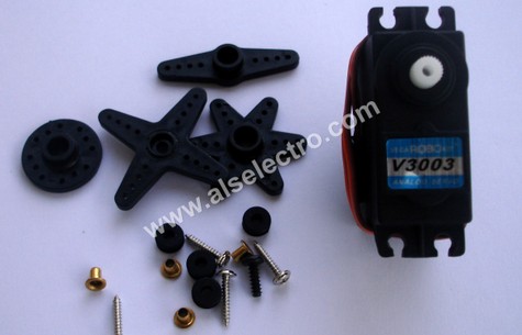
Servo Motor
V3003 ( PLASTIC GEARED )
Operating Voltage : 4.8-6.0V
PWM Input Range : Pulse Cycle 20±2ms, Positive Pulse 1~2ms
STD Direction : Counter Clockwise / Pulse Traveling 1500 to 1900µsec
Stall Torque : 3 Kgf.cm(41.3 oz/in) at 4.8V, 3.2 Kgf.cm(44 oz/in) at 6V
Operating Speed : 0.2 sec/ 60° at 4.8V, 0.18 sec/ 60° at 6V at no load
Weight : 38g (1.27 oz)
Size : 41.320.338.748.510
Plug Available : FUT, JR
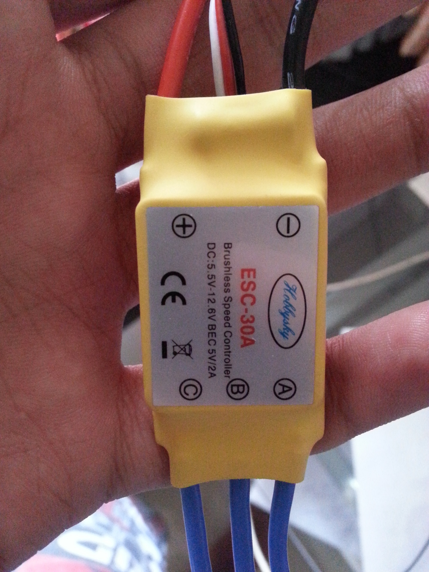
ESC
Hobbysky ESC 30A
DC:5.5V-12.6V
BEC 5V/2A
Battery
Turnigy lipo battery 11.1V
20-30C
3000 mAh
Need to run the brushless motor and servo using the pc keyboard using Xbee S1 modules.
Is it okay to connect the red wire from the ESC connector to the arduino's +5V pin?Will it power up the arduino ?Is it also possible to run the servo from the same battery by splitting the red wire from ESC for both arduino and Servo?
I hope somebody could give an idea about using the lipo battery for the whole setup because i read on most threads that the red wire from the lipo shouldnt be connected to the arduino +5V pin.

Above I have displayed the images files attached below.
Is it okay to connect the red wire from the ESC connector to the arduino's +5V pin?
No. The ESC sucks too much current.
Will it power up the arduino ?
The red wire is a power IN wire. It powers the servo part that makes the ESC change output voltage. It is not a power OUT wire.
Is it also possible to run the servo from the same battery by splitting the red wire from ESC for both arduino and Servo?
From what same battery?
Get your space bar fixed. There needs to be spaces after punctuation symbols.
PaulS:
The red wire is a power IN wire. It powers the servo part that makes the ESC change output voltage. It is not a power OUT wire.
It IS a power out wire.
The ESC has a Battery Elimination Circuit (BEC) with can source 5V @ 2A. It's VERY common to use this power for controllers and servos.
2A should be okay to power both the Arduino and the servo.
VinayV:
Is it okay to connect the red wire from the ESC connector to the arduino's +5V pin?Will it power up the arduino ?
Yes. This is want the 5V BEC is for.
VinayV:
Is it also possible to run the servo from the same battery by splitting the red wire from ESC for both arduino and Servo?
Probably (take that as a yes). You don't want the 5V to pass through the Arduino board. Split the power from the BEC to both the servo and the Arduino.
The main problem with powering the Arduino and the servo from the 5V BEC is the servo could cause problems for the Arduino. (I do this sort of thing all the time though.)
VinayV:
I hope somebody could give an idea about using the lipo battery for the whole setup because i read on most threads that the red wire from the lipo shouldnt be connected to the arduino +5V pin.
Just to be clear, we're talking about the red wire on the servo type connector of the ESC?
There's considerable debate about this. If you have more than one ESC, it's a good idea not to have the various BEC outputs connected. Lots of voltage regulators don't work well when used in parallel.
If you are powering the Arduino from an external source through the barrel jack, then you wouldn't want to connect the BEC to the 5V pin of the Arduino. In this situation, it's okay since the BEC is the Arduino's only power source.
I'm not so sure if it's okay to leave the BEC connected while the Arduino is connected to a PC via USB. I generally disconnect the BEC when programming the Arduino.
Thanks for posting your images inline.
Spaces go after question marks not before. Strange punctuation is very annoying to us older guys. Speaking of annoying, "I" is ALWAYS capitalized when it's used to identify yourself.