Hi,
I started working on an Arduino Uno Colour Sensor Project today, where I essentially have two motors and an RGB sensor; Programming those sensors to rotate based on a colour range that is read by the RGB sensor.
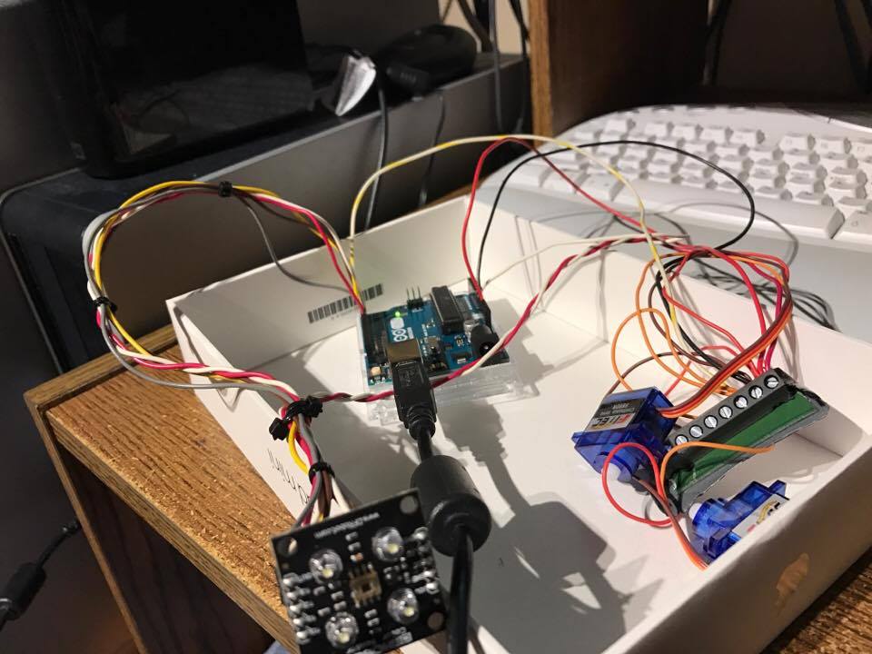
I have thus far connected all of the components to all of the sensors, testing the voltage supplied to each component to ensure that each item was receiving power. Everything seems to work and I followed the schematics provided by the manufacturers for both the servo and the TCS3200 sensor. (Links below). Where each pin has been assigned to the exact same pins as the diagram.
I can't seem to, however, get any of these components to work. I've tried using the sample code posted on the manufacturers website for the RGB sensor for example, and the LEDs that are supposed to shine, do not shine. I truly need help moving this project forward.
When I try to compile the code, I receive some ASCII values. Not sure why this is as well.
I've attached a photo of the described circuitry.
Note: I am a beginner with Arduino, however, I have previous programming knowledge in C, C++ and Swift.
My Circuit: http://imgur.com/a/rKVrs
Color Sensor: TCS3200_Color_Sensor__SKU_SEN0101_-DFRobot
if you run verify code without errors but upload fails check arduino ide com port settings
There are no errors, though. It just outputs a bunch of ASCII characters. Windows detects the Arduino and the port is set to the correct one in IDE. Not sure what the issue is still.
Hi,
Welcome to the forum.
Please read the first post in any forum entitled how to use this forum.
http://forum.arduino.cc/index.php/topic,148850.0.html then look down to item #7 about how to post your code.
It will be formatted in a scrolling window that makes it easier to read.
I'm afraid this is not a circuit diagram.
Can you please post a copy of your circuit, in CAD or a picture of a hand drawn circuit in jpg, png?
Thanks.. Tom.. 
Hi,
Until you get the colour sensor example working, do not try and do anymore of your code.
You need to do it in stages.
The colour sensor is the first.
Tom...
Hi,
This may be an easier tutorial and code, using serial monitor.
Tom...
The two circuit diagrams that I followed include these two provided by the manufacturers. Is there a way for me to test if the data is coming through properly from each sensor? I know that power is being supplied to each sensor. I also checked my port settings on my complier for the serial monitor, everything seems to be working.
RGB to Circuit: Imgur: The magic of the Internet
Servo to Circuit: Imgur: The magic of the Internet
Thanks.
Hi,
Did you reae post #4 and #5, get the sensor working first, forget the servo.
Try the examples, you should not use pin 0 for a servo, it and pin1 are for programming the UNO.
Also please attach your files, use REPLY and you will see it has at the bottom of the screen an ATTACHMENT facitiy.
Thanks.. Tom..
Can you tell us your electronics, programming, arduino, hardware experience?
Yes, I did read 4 and 5. I tried everything you said. No luck.
The data signal still doesn't seem to be there. Any suggestions?
As stated in my original post, I have programming experience in C, C++ and Swift. I have worked on circuits before as well. This is my first Arduino Project.
Hi,
Do you have a DMM, check that 5V is getting to the sensor board.
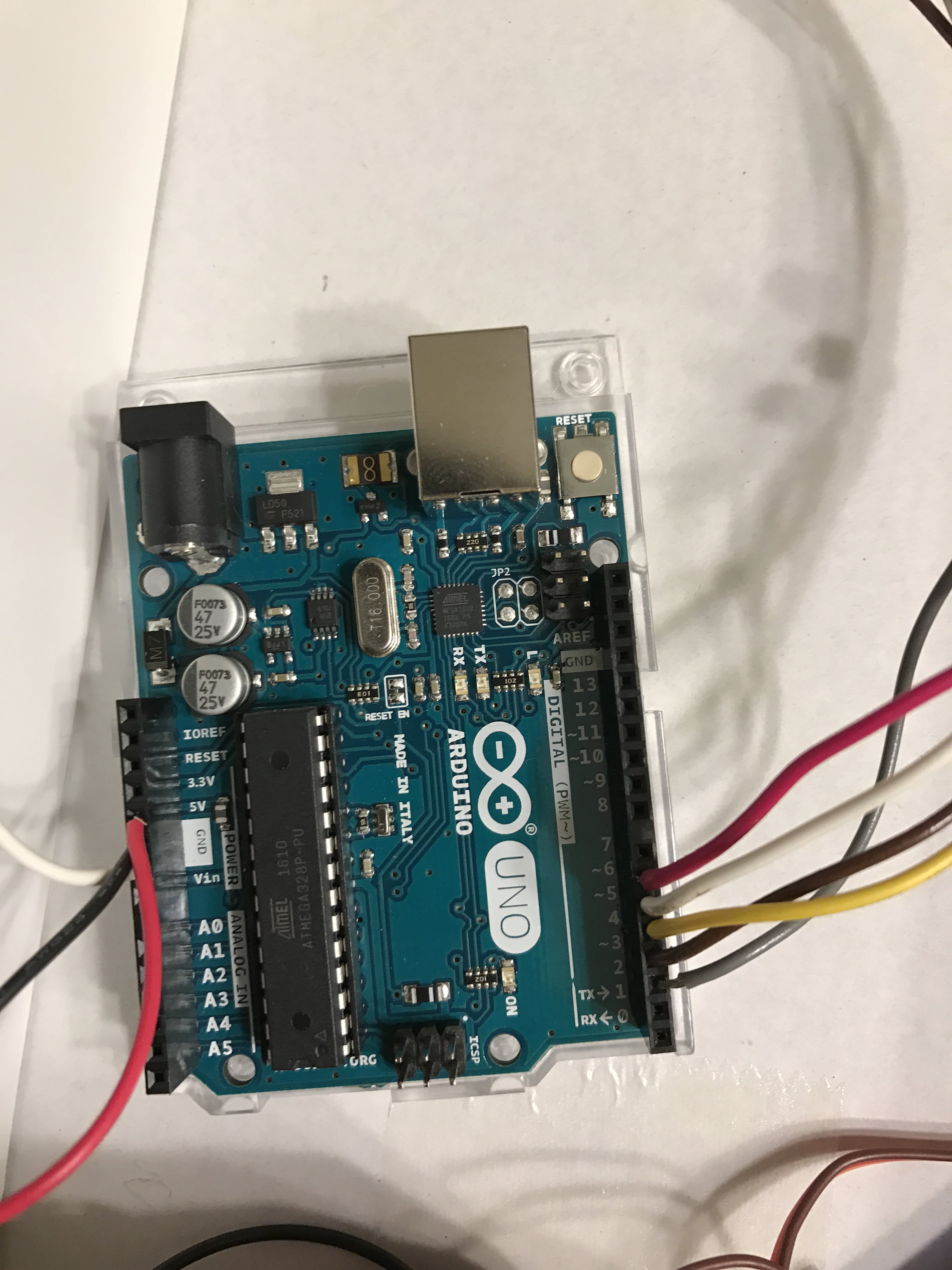
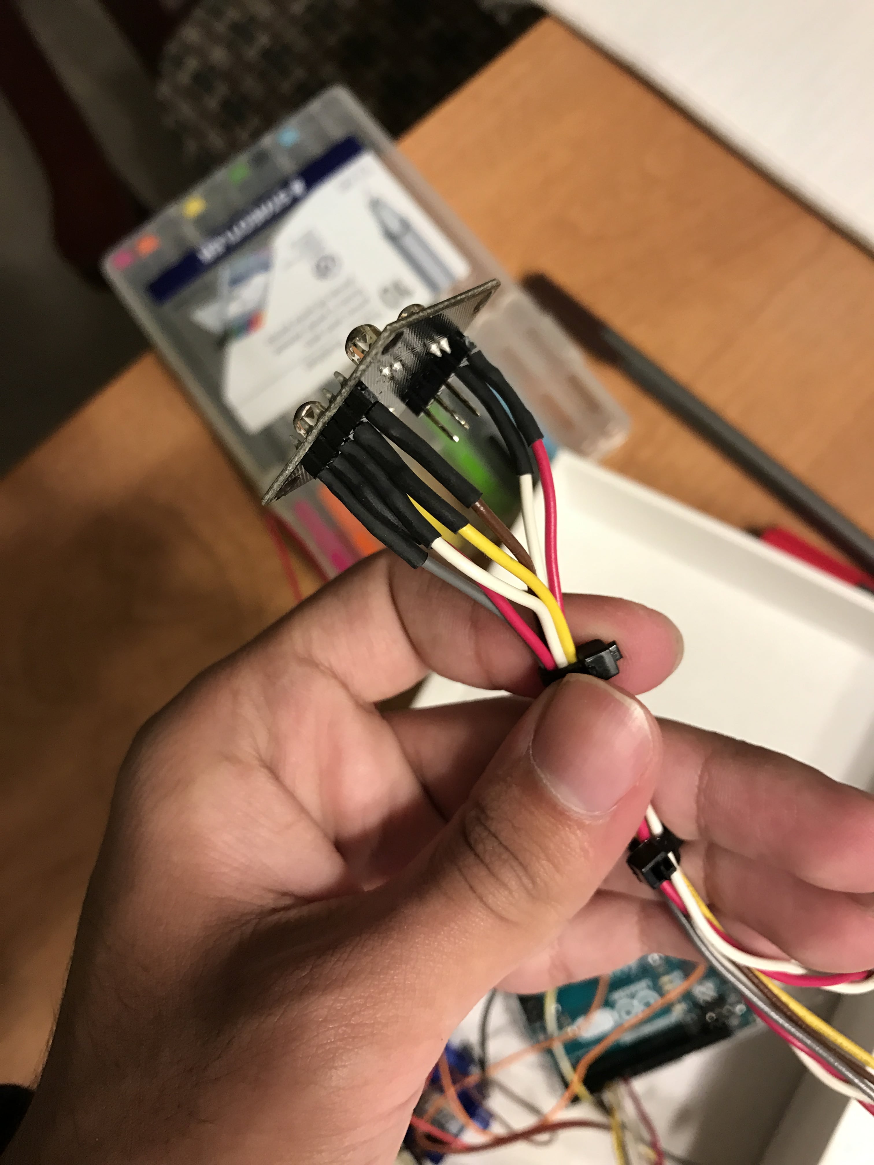
Can you post colose-up pics of your connections to the sensor board and and another pic of your connections to your UNO.
Thanks... Tom...
I used a voltmeter to determine if the the 5V was getting to the sensor. Here are some close up photos. Do you see anything wrong other than the data going to the digital 1 port (used for programming the Arduino), I tried the digital port 5 as well after taking the photo, didn't work.
Thanks.
Hi,
Can you post the program you are using to test the sensors, just the sensors, no servo connected or even mentioned in the code?
Then we can advice you.
Thanks... Tom..
I'm using this sample code provided by the manufacturer of the sensor. The sensor does not seem to light up.
Thanks,
int s0=3,s1=4,s2=5,s3=6;
int out=2;
int flag=0;
byte counter=0;
byte countR=0,countG=0,countB=0;
void setup()
 {
 Serial.begin(115200);
 pinMode(s0,OUTPUT);
 pinMode(s1,OUTPUT);
 pinMode(s2,OUTPUT);
 pinMode(s3,OUTPUT);

 }
void TCS()
 {
 flag=0;
 digitalWrite(s1,HIGH);
 digitalWrite(s0,HIGH);
 digitalWrite(s2,LOW);
 digitalWrite(s3,LOW);
 attachInterrupt(0, ISR_INTO, CHANGE);
 timer0_init();

 }
void ISR_INTO()
 {
 counter++;
 }
 void timer0_init(void)
 {
  TCCR2A=0x00;
  TCCR2B=0x07;   //the clock frequency source 1024 points
  TCNT2= 100;    //10 ms overflow again
  TIMSK2 = 0x01; //allow interrupt
 }
 int i=0;
 ISR(TIMER2_OVF_vect)//the timer 2, 10ms interrupt overflow again. Internal overflow interrupt executive function
{
    TCNT2=100;
    flag++;
 if(flag==1)
  {
    countR=counter;
    Serial.print("red=");
    Serial.println(countR,DEC);
    digitalWrite(s2,HIGH);
    digitalWrite(s3,HIGH);
  }
  else if(flag==2)
   {
    countG=counter;
    Serial.print("green=");
    Serial.println(countG,DEC);
    digitalWrite(s2,LOW);
    digitalWrite(s3,HIGH);
   }
   else if(flag==3)
    {
    countB=counter;
    Serial.print("blue=");
    Serial.println(countB,DEC);
    Serial.println("\n");
    digitalWrite(s2,LOW);
    digitalWrite(s3,LOW);

    }
    else if(flag==4)
     {
     flag=0;
     }
       counter=0;
}
void loop()
 {
  TCS();
while(1);
 }
Hi,
In the diagram of your sensor it shows the LEDs need to be turned on by the LED pin on the PCB being pulled HIGH.
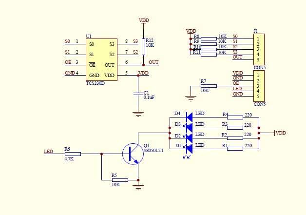
So you will need to allocate a UNO pin as an OUTPUT and connect the LED pin of this output.
Then add;
pinMode(x, OUTPUT); //  make X the number of the output pin connected to LED pin on PCB
digitalWrite(x, HIGH);
Serial.println("LEDs ON");
Put this in the last part of the setup code.
Replace X with the pin output number of the UNO.
This should turn the LEDs ON. I'm not sure how much current, it draws, but your USB should be OK.
Make sure you have the baud rate in the IDE monitor set to 115200.
Hope it helps.. Tom..
Thanks for the help, but still no luck. The code below is what I tried. Still can't get the RGB sensor to light up. Do you think it's a problem with the Arduino Uno itself?
Thanks, again
int s0=3,s1=4,s2=5,s3=6;
int out=2;
int flag=0;
byte counter=0;
byte countR=0,countG=0,countB=0;
void setup()
 {
 Serial.begin(115200);
 pinMode(s0,OUTPUT);
 pinMode(s1,OUTPUT);
 pinMode(s2,OUTPUT);
 pinMode(s3,OUTPUT);
pinMode(out, OUTPUT); //  make X the number of the output pin connected to LED pin on PCB
digitalWrite(out, HIGH);
Serial.println("LEDs ON");
 }
void TCS()
 {
 flag=0;
 digitalWrite(s1,HIGH);
 digitalWrite(s0,HIGH);
 digitalWrite(s2,LOW);
 digitalWrite(s3,LOW);
 attachInterrupt(0, ISR_INTO, CHANGE);
 timer0_init();

 }
void ISR_INTO()
 {
 counter++;
 }
 void timer0_init(void)
 {
  TCCR2A=0x00;
  TCCR2B=0x07;   //the clock frequency source 1024 points
  TCNT2= 100;    //10 ms overflow again
  TIMSK2 = 0x01; //allow interrupt
 }
 int i=0;
 ISR(TIMER2_OVF_vect)//the timer 2, 10ms interrupt overflow again. Internal overflow interrupt executive function
{
    TCNT2=100;
    flag++;
 if(flag==1)
  {
    countR=counter;
    Serial.print("red=");
    Serial.println(countR,DEC);
    digitalWrite(s2,HIGH);
    digitalWrite(s3,HIGH);
  }
  else if(flag==2)
   {
    countG=counter;
    Serial.print("green=");
    Serial.println(countG,DEC);
    digitalWrite(s2,LOW);
    digitalWrite(s3,HIGH);
   }
   else if(flag==3)
    {
    countB=counter;
    Serial.print("blue=");
    Serial.println(countB,DEC);
    Serial.println("\n");
    digitalWrite(s2,LOW);
    digitalWrite(s3,LOW);

    }
    else if(flag==4)
     {
     flag=0;
     }
       counter=0;
}
void loop()
 {
  TCS();
while(1);
 }
I have programming experience in C, C++ and Swift.
Sorry but it doesn't show in that code.
- You can't print inside an ISR
- All variables used in an ISR that are also accessed outside it must be declared as volatile.
- Your loop function is just a bastardisation of the setup / loop function. Just move the TCS function call into the setup function and leave the loop function empty. Except once you do that it won't print anything because as I said you can't print inside an ISR.
If you had read the initial post thoroughly, this is sample code taken straight from the manufacturer.
Hi,
Did you connect UNO pin2 to the LED pin on the sensor board.
If so measure the voltage on that pin when you run the program.
Tom...
alimalik:
If you had read the initial post thoroughly, this is sample code taken straight from the manufacturer.
Read it again and I feel it is ambiguous but if that is right:-
Wow, what utter crap from a manufacturer, it could never work. You would have thought they would have tested it. So someone to avoide then.