I am trying to make a robotic arm with 3 60RPM Dc geared motors and 1 MG90s Servo motor for which I am using the L293D motor shield and Hc-05 bluetooth module to control via an app. I am having trouble with the circuit diagram, Can anyone help me by identifying any fault in the circuit diagram given below? By the way, the power supply is a 12V 10A SMPS to the motor shield and a buck convertor is used to power the bluetooth module from the same SMPS. The motor shield is mounted on top of the Arduino UNO and is shown seperately to show the connection only

1 Like
Welcome.
Your topic has been moved. Please do not post in "Uncategorized"; see the sticky topics in Uncategorized - Arduino Forum.
L293D provide current lower as 1A.
HC-05, even with Uno's 5V connected, consume less as 200mA.
So, 10A power supply is a little overkill.
(L293D need 5V too)
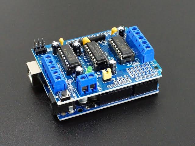
do you have a photo?
But the 10A smps was not selected for this special purpose. It was selected for versatality of use. The Arduino 5V is not used for hc05 because it was fluctuating and HC05 was not turning on when connected to the Arduino board 5V pin. I Just wanted to know the connection of L293D and HC 05 with SMPS is correct or not. The pin congfiguration and grounding. The circuit diagram which I used to connect the components is given, please have a look
The L293D is supplied with 12V supply and Hc05 with buck convertor

So do you see any fault in circuit diagram
Are there any problems in grounding or anything else which is seen in the circuit
???
The power supply issue, do you see any problem with the circuit connections
One doubt, the L293d is supplied with a 12V connection, why would it need a 5V from arduino
not from arduino, but from buck converter. chip itself need 5V for intern logic circuit. read datasheet.
do you have a photo? or link where you buy it ?
Yes, from the buck the HC05 is connected 5V, the Bluetooth module is working fine with the circuit, but the motors aren't receiving signal
I bought it from a local store
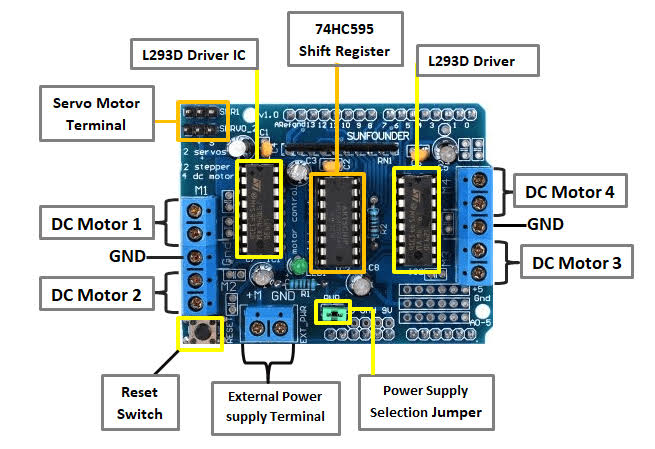

look on IC1 and IC2 pin8 is voltage for motors and pin16 is voltage for logic it is connected with 5v pin of arduino.
did you already show your sketch?
I'm sorry I don't understand the logic much because I am not from electronics background and this is my second try on an Arduino project. I am acquiring the required information but missing some in between.
anyway, in post#6 you see corrected schematic. mark as solution.
Post#6 or Post#16